
Thread: Quite an Unusual one
-
02-04-2015 #161

 Last Activity: 1 Day Ago


 that creation of yours is exactly what inspired me for my Z
 Originally Posted by Jonathan

First of all all steel there was laser cut and holes laser drilled, which helped a lot /0.01-0.03mm accuracy of all cut pieces/. Then the aluminum pieces were machined <0.01mm Originally Posted by Jonathan
So knowing that the aluminum pieces were precise, i mounted first the rails on the separate side pieces, checking them to be tight corner fit against another piece of aluminum and straight edge. Later i mounted the 3 sides of the box using , straight edge, precise squares and digital caliper. So now i knew they were parallel to each other in all planes, /same distance/. Then i checked if the spindle enters and it was tight fit just easy enough to slide.
That told me till here everything is perfect/ cause the spindle was machined before 99.8mm OD. We were at the point of machining it and checked it against DTI and it seemed it was not necessary. That is the "good" original spindle with the 4 bearings.
Then knowing that the spindle box is mounted together under 0.01mm i just screwed to the side bearing blocks the side steel plates checking them flat and square against flat surface. Then i used some small clamps to not let them move back and forth.
So as all was mounted together maintaining that precision i laid it down carefully on top of the back Z plate. Now as you can guess the Z plate was not perfectly flat. So i spot welded the side plates/together with the aluminum assembly/ to the Z plate, but only at one side that so the previous assembly is square left right. See pictures above. I used also some clamps not to let it twist left right. Then i force clamped all down to the steel back Z plate , so now it was square and flat / cause the steel side plates wer cut by laser 0.01mm , remember? and i have mounted them perfectly flat against flat plate/ .
So now all was 0.01mm mounted together. I just carefully soldered spot by spot, careful not to heat the bearing blocks.
Later i took out all the aluminum assembly together with the bearing blocks and painted the steel assembly , masking the sides where the bearing blocks were meant to enter later So at certain places there is no paint, to ensure tight fit and not spoil the accuracy.
Same must be done for the back at the place where the ball screw nut housing on the gantry will be fixed to the back Z plate. I just left 1mm space in the drawing, to be shimmed, but due to 1mm less epoxy height, it was tight fit.
What i would say that a sincere judging helps here, one should not lie to himself and want to speed things, cause these are the moments where accuracy may be lost and accumulated.
So I fit the steel Z assembly to the gantry and squared it using the vertical Z bearing block surfaces to a straight edge across the long rails. Then i resquared the gantry ball screw, loosening it, going one end, tighten, going another end tighten and repeat. This to have the Exact same travel as the rails
So when i fit the aluminum assembly i had only to square it front back/ again using the long straight edge across long rails. See photo above. Then tightened the bearing blocks to the . That simple.
Something should be clear though. everything was designed to fit together using only 2 precision squares and 1m and 2m straight edges. No dial indicator was necessary at any moment. Everything was judged by the tight fit of the squares to surfaces and straight edges. I did so with the first machine i build and achieved 0.01mm precision.
So basically i will not use DTI until the moment i have the machine running. from experience it seems i can notice with naked eyes 0.05mm gaps without problem against the straight edge/ the epoxy story/ so i am happy that everything is tight fit.
When all ready i will check with dti and straight edge and report. But for now it seems i maintain the same precision as the first build and on that size of machine, well ... i am happyLast edited by Boyan Silyavski; 02-04-2015 at 01:18 PM.
-
02-04-2015 #162

 Last Activity: 19-01-2024
Now now Boyan.!!! . . You contradict your self about lieing to one's self here with this statement.!! . . . . Your fooling your self if you think you can see "Five one hundreth's Gaps" with naked eye over the length or width of this machine. Originally Posted by silyavski
Last Activity: 19-01-2024
Now now Boyan.!!! . . You contradict your self about lieing to one's self here with this statement.!! . . . . Your fooling your self if you think you can see "Five one hundreth's Gaps" with naked eye over the length or width of this machine. Originally Posted by silyavski
Not saying your machine isn't or won't be accurate because I know it will or you will make it so. But I must say think your going to be surprised when time comes to cutting just how far out of Tram that spindle will be if you don't put a DTI on it. I also think it will be Bitch to setup looking at the pics.!!
-
02-04-2015 #163
Last Activity: 1 Day Ago
What i meant was i can spot the 0.05-0,1 mm gap between a straight edge and something, say rail or other flat surface. Not that i can spot if the machine is straight or not over all its length or width. I spent a week just making sure the long rails are mounted straight and flat, not counting the epoxy.
Yeah, without DTI its difficult to say more.
What do you mean to tram the spindle? Its trammed already using 2m straight edge and squares. There will be no more tramming until the moment i cut some square aluminum shapes and first i make sure the gantry is squared by the limit switches and later do some stuff and see if there is something off judging by the final dimensions of the work.
Then the bed would be surfaced or head trammed first, but only if i am off by a great deal, depends on what results tell me. It is very easy in fact to tram it all as i always followed your advice of adjust ability making all through holes bigger.
Now about the DTI. I could clamp it now on one side rail and move the head assembly up down and see what DTI says but ... ok i went and clamped it. It says nothing, i mean i mounted all very well only using the squares and edge. Unbelievable but true.
I will power the whole thing then check and readjust if necessary, cause its very difficult to move all by hand. long distances i mean and i get bored.
At the end even if vertically is off with 0.1mm on 200mm travel/ which is not the case/, this is nothing. on 20mm aluminum sheet the inclination would be 200/20=10, so 0.01/10=0.01mm
-
02-04-2015 #164
Last Activity: 19-01-2024
You will tell instantly if the spindle is trammed correctly or not when you surface material with a wide cutter. If off then you'll get steps and it doesn't take much error to get steps. The pictures make it look difficult to get at bolts if shimming is needed etc.
-
11-04-2015 #165
Last Activity: 1 Day Ago
Now comes one of the last parts. I frankly admit i was quite indecisive there, from the beginning of the design. So it was time to sit on my arse and make some calculations and think the things clearly.
The working area / table bed. May be it a theme for a whole new topic. i see many people are wondering how to do it differently than plywood, especially if they mean to cut aluminum and cool it.
Now lets be clear i am not talking about the machine bed structure nor the sacrificial board. I am talking about the working bed/fixing area and method which is in between the frame and the sacrificial board and which is water/coolant resistant and is strong enough for moderate aluminum milling
So lets see the options. prices are Spanish, but may be more or less the relations will keep in different countries. Some thickness prices are not known but can be extrapolated. 1kg of steel is ~1 euro, 1kg of aluminum 6082 is ~5euro,
-phenolic 10mm thick 65euro/m2 so as i see it needs to be minimum 20mm best 30mm thick ...
-marine ply wood 15mm thick ~36-50 euro per m2 , i see it needs to be at least 30mm thick.. so its good for a spoil board but expensive for top
-marine ply wood with phenolic top for truck flooring, now this is a good one, but its even more expensive and the phenolic will be very thin to surface
Now instead of writing here i have made some drawing with data for the better options:
I have spent all morning in calculation and last days rethinking the things. So for me its clear:
My choice will be UPN140. I have the bed clearance for it. It is cheap and very strong for the money. Like the last photo, 2 welded together, with T channel and DIY Tee nuts as per drawing. So i will drill a lot of holes and use them for fixture and big sheets will be fixed with clamps that will pass trough the channels. It will be screwed to the table with nuts that pass between the connection of 2 of the UPN. I will have to find a resistance welder from somewhere for clean job.
Note: Moment of inertia is x axis cause its in C position when measures are given, so a bit misleading. Anyway, its in the good for us direction.
last thing that i have not clear is if i will machine it both sides and machine the bed bellow, so all is flat when mounted and dismounted if needed. I am seriously starting to think to somehow mount a grinder on the Z or surface all using small bit, slow speed and coolant. i said before no steel work with that machine, but its quite tempting. And from what i have seen people have done it with much weaker designs.
One thing i know is that on top of that UPN140 i will use then thin phenolic sheet or even better scrap pieces, for sacrificial board. At leats on some part of the machine. On other i will use cheap expanded PVC sheet.
I hope that these calculations money/material/ strength will help people to evaluate properly what exactly bed they need.
Notes
-UPN profile can be cast filled with cement which will make things even better. Non crack cement for table tops and garage floors is enough for that.
-aluminum T channels are damn expensive so i did not even consider them. Even steel channels are very expensive, crazy.
PS2.
One question . For the the threaded holes to be closed to keep them clean , what is the name of the screw that is like a grub screw but is for flat screw driver?Last edited by Boyan Silyavski; 11-04-2015 at 02:51 PM.
-
The Following User Says Thank You to Boyan Silyavski For This Useful Post:
-
12-04-2015 #166

 Last Activity: 18-11-2020
I believe it is called SLOTTED GRUB SCREW. Originally Posted by silyavski
Last Activity: 18-11-2020
I believe it is called SLOTTED GRUB SCREW. Originally Posted by silyavski
-
19-04-2015 #167
Last Activity: 1 Day Ago
OK. Some development.
Did i tell you that i plan to add plasma to the machine. Front half for machining, back half of table for plasma. Or whatever life commands,
I know, old China HF plasma no good, combined machines no good... I can say yes, shoot 2500 euro and tomorrow a brand new Hypertherm Powermax 45 will be at my door.
First i have to know if that will pay off where i live, for what i do and so on. However instead i decided to start with what i have at hand, slowly make my way around. I did not skip the THC though as i believe it will be extremely important especially on a combined CNC table like mine.
I did my research and decided to go with the Neuron THC. I skipped the simple THCs where there were no advanced controls. Vietnamese and similar were out of question due to lack of support or support in some strange language.
The ones who are into plasma cutting know the choice is not so big money wise and feature wise. Razordance THC is only for Hypertherm, then there is the Proma, mini THC that looked promising, Cadcnc and Neuron. Or you pay big dollar. Cadcnc and Neuron seemed the most advanced. I as many times at the point of buying something from Cadcnc but the fact that he is in USA, his stuff works bundled together, some of his ridiculous policies mad em not do it. So the Neuron it was.
I will make a separate review when all is working, but i would say the documentation and the support from Andrey till now is outstanding. And to tell you the truth that the most important thing when you start doing something that you do for first time and you don't know nothing about.
So the Neuron THC lite came at home after customs delay /Russia is not EU you know /.
Thats the Plasma, tig, arc. German controlled Chinese machine with 5 year warranty.
First thing i changed the cover screws cause i decided i would open it quite frequently :-)
Then i twisted some pairs of wire for the voltage divider /1mm2 >600v wire, as per recommendation of Neuron manufacturer / :
Then i blowed the dust of the insides, by the way on the box says to do that 2 times per month
Here is my DIY drier for the plasma, painting and for blowing dust. No body would want to blow some drops of water on electronics, right. 10" filter box and 1/2kg of desiccant. Black plastic tube in the middle with a lot of holes so air can pass. On the right is a last stage lubricator outlet for air tools. Thre dry air outlet is in the middle
The insides, with the Neuron mounted, arc ok mounted , RJ45 ethernet communication cable. meanwhile i bout and learned to use cable connector making tools. as it seems Ethernet is the future.
The shed in front of the garage, the welding table and the machine bed arrived. I alsmost finished all till today, though run out of gas, otherwise i would have been welding right now. Will take more pictures when ready. the rage saw cut the UPN 140 like a charm. I was for worried for a moment when all arrived cause i forgot to check if the saw could do that wide
i need a welding table to make my welding table, isnt that funny
Last edited by Boyan Silyavski; 19-04-2015 at 07:13 PM.
-
12-07-2015 #168
 Last Activity: 05-01-2016
Amazing build Boyan, those rage saws are quite the beast aren't they. Originally Posted by Boyan Silyavski
Last Activity: 05-01-2016
Amazing build Boyan, those rage saws are quite the beast aren't they. Originally Posted by Boyan Silyavski
Do you have an update and more pics of how the build is progressing, this has got to be one of the best build logs I've seen, it would be shame for it to stop before we get some video of the finished thing in action!
-
12-07-2015 #169
Last Activity: 1 Day Ago
HI,
yes i have an update.
First one of the piles of steel at the previous photos now is welding and fabrication table, the other pile with the long pieces now is a shed in front of my garage where the machine is. At the link above you could get idea how to fix the UPN to the bed

Now about the machine itself. Cables mounted and ready to run. I had some problems fitting the cables cause i made the error underestimate how big cable chain i need. I had some serious cable chain but it seems i needed even bigger.
Some of the encoder cables were shorter so i had to invent here also. Most cheap was to use HDMI cable, i hope it lasts some time.
Now the biggest problem. I can still not make run the machine. Reason being that although all is connected and programmed from Mach 3 side and from Galil side it would not move.
So i read 10 times the servo and the Galil manual / each 400 pages/. At the end frustrated i started trouble shooting. Checked 1 by one all cable connections cause the servos were tripping, cleaned contacts...this took a couple of days. At the end i discovered that when programming the servos somehow i missed to program correctly the motor name of 2 of them, hence the problems. So more or less all is ready here, still have 1 enable wire to 1 of the servos not working well so i have to rewire that.
Jogged the servos from the software and tuned them for a second.
That servos are incredibly fast, smooth and silent. The machine moves like crazy fast super silently. I directly jogged the Z assembly left right on the gantry 10-15m per min. Its scary.
Good that the frame is balanced horizontally. yeas i have 10 cm deviation on the floor so i used 30-35 square wood pieces leveled them and the machine is on top of them.
So the machine should be running any minute but 2 weeks i couldn't manage to make the Galil board work. Yes, it works communicates, switches signals and so, but still not able to make it speak / pulse/ to the servos. And on top of that i burned the COM port from changing cables. So i could not now change the servo type of signal expectancy. GRrrrrrrrrr!! Now have to wait for new COM board cause where i live...
I asked about help with the Galil at Mach forum, Galil forum, nobody... So after 2 weeks i discover that i have to issue MT command to change the type of pulse it sends. It may be the greatest board but with nonexistent support, no schematics of connection... maybe i did a mistake not contacting directly support, but from what i saw in their forum-please read the manual its explained there. yes its f***ng explained but its 400 pages manual and i am reading 3 of them at once and on the way learning new terms that i had no idea yesterday what that even means, so a bloody connection diagram for every application example and step by step instruction would be great for stupid people like me and the 20 engineers that asked the same questions...
So i am still stuck, last effort these days, then it goes off the machine cause i will receive 2 Pokeys boards, so one goes there. Will leave the Galil apart, mount it in another box , study it and use it in another machine. And then bloody sell it :-)
So any day soon it will be fully alive, then i will move the gantry around and mount and level the ready UPN140 pieces for the working table bed to be level, Thats why i need to move the Z around so i measure and shim where necessary.

Here where is the PC, the VFD and so on, at the entrance. Switch on the machine,mount piece, Mach3, program run, then go out and close garage door. The garage=Big enclosure for the machine
Last edited by Boyan Silyavski; 12-07-2015 at 08:42 AM.
-
The Following 2 Users Say Thank You to Boyan Silyavski For This Useful Post:
-
28-07-2015 #170
Last Activity: 18-11-2020
Looking good!
How did you end up mounting UPN140 for the bed? I mean how did you get it level? Or you just have them laying on the machine for the moment?

 Reply With Quote
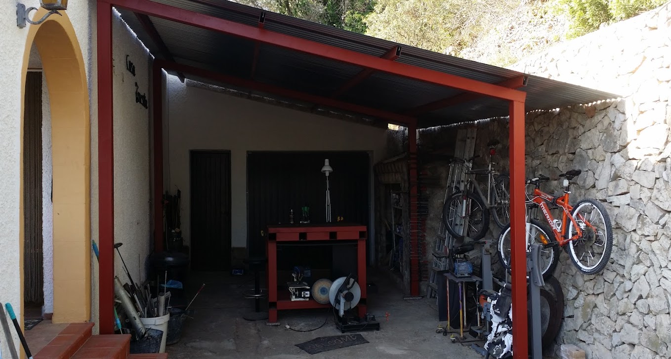
Thread Information
Users Browsing this Thread
There are currently 1 users browsing this thread. (0 members and 1 guests)

Bookmarks