
Thread: Emco PC120 Turn
-
03-08-2016 #21

 Last Activity: 6 Days Ago


 Thanks. I tried to put on a dial gauge last night but space is an issue. I need a smaller setup.
 Originally Posted by m_c

In terms of home position, I am hoping that with electrical proximity switches, this will be fairly accurate. I will do some tests later.
On the sensor for the spindle, I noted what I recall to be 3 wires coming out from the sensor. Let's assume this is a single pulse (or needs to be converted somehow), is there normally an input into the BOB or similar to read these? If the sensor is damaged, is there a part that can be bought that will give me what I need (like a generic generator that works with most setups)?
Many thanks for your help / info, been very useful.
-
03-08-2016 #22
Last Activity: 1 Day Ago
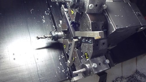
 Where the cutting edge is, and what direction the material has to turn in relation to the cutting edge. The turret on my lathe is rear mounted with the disc machined so 12mm tools have their cutting edge level and facing down when at the spindle (click the pic if you want to see a vid of it changing position a couple times) Originally Posted by Chaz
 Avoiding the rubbish customer service from AluminiumWarehouse since July '13.
-
03-08-2016 #23
Last Activity: 6 Days Ago
Sorry, my question was unclear. Originally Posted by m_c
I understand when I need CW and when CCW. What 'setting' tells the spindle to rotate CW or CCW depending on the tool choice?
-
03-08-2016 #24
Last Activity: 1 Day Ago
There's not a setting for that. You'll need to ensure however you produce your G-code does the spindle direction setting. Originally Posted by Chaz
You could allocate blocks of tool numbers that rotate certain directions, then use the M6 macro to check and set spindle direction depending on tool number.Avoiding the rubbish customer service from AluminiumWarehouse since July '13.
-
03-08-2016 #25
Last Activity: 6 Days Ago
Great, I was thinking it might be CAM based. Ill check the settings in Fusion 360. That said, if I run everything 'upside down', I can stick to CW which suits drilling ops. Will also save me from buying a new 16mm boring bar as I can use what I have. Originally Posted by m_c
-
07-08-2016 #26
Last Activity: 6 Days Ago
Struggling with two items.
Spindle, doesnt like the one plugin. It works oddly if I disable the plugin but then not on restart of Mach. Ive tried the Matty Zee plugin, seems to work, the drive 'stops' if the start up speed is too high (I need to slow down the ramp time perhaps), and the motor speeds / what mach3 thinks its doing dont match. I dont have feedback on the motorspeed at the moment.
The main other issue is that Fusion CAD is putting some odd code in which is causing me to hit limits. The consensus is to use the Fanuc turning Post Proccesor. It works, no errors, but I get this:-
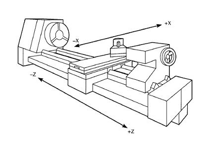
I'm less knowledgeable on turning code than milling however what I dont understand is why its moving to X33 in this line - N20 G0 X33. Z1.414. The way my lathe works is X is a negative number at the top and it should be moving to zero. So X-32 will be my current location when homed up top. This is a slant bed lathe, would this be correct? Ive tried to reverse the X direction in the setup on Fusion but gives me the same output.
%
O1001
N10 G98 G18
N11 G21
N12 G50 S6000
N13 G28 U0.
(FACE1)
N14 T1313
N15 G54
N16 M8
N17 G98
N18 G50 S3000
N19 G96 S200 M3
N20 G0 X33. Z1.414
N21 G1 X15.828 F1000.
N22 X13. Z0.
N23 X-1.6
N24 X1.228 Z1.414
N25 G0 X33.
(PROFILE1)
N26 M9
N27 G98
N28 G50 S3000
N29 G96 S200 M3
N30 G0 X33. Z1.345
N31 X14.968
N32 G1 X14.828 F1000.
N33 X12. Z-0.069
N34 Z-6.55
N35 X12.98
N36 X15.808 Z-5.136
N37 G0 Z1.404
N38 X13.828
N39 G1 X11. Z-0.01 F1000.
N40 Z-6.55
N41 X12.
N42 X14.828 Z-5.136
N43 G0 Z1.404
N44 X12.828
N45 G1 X10. Z-0.01 F1000.
N46 Z-4.775
N47 G18 G3 X11. Z-5.798 R1.3
N48 G1 Z-5.8
N49 X13.828 Z-4.386
N50 G0 Z1.404
N51 X11.828
N52 G1 X9. Z-0.01 F1000.
N53 Z-4.535
N54 G3 X10.5 Z-5.034 R1.3
N55 G1 X13.328 Z-3.619
N56 G0 Z1.404
N57 X10.828
N58 G1 X8. Z-0.01 F1000.
N59 Z-4.5
N60 X8.4
N61 G3 X9.5 Z-4.622 R1.3
N62 G1 X12.328 Z-3.208
N63 G0 Z1.404
N64 X9.828
N65 G1 X7. Z-0.01 F1000.
N66 Z-4.5
N67 X8.4
N68 X8.45
N69 X8.5 Z-4.501
N70 X11.328 Z-3.087
N71 G0 Z1.404
N72 X9.279
N73 G1 X6.45 Z-0.01 F1000.
N74 Z-4.5
N75 X7.5
N76 X10.328 Z-3.086
N77 G0 Z1.404
N78 X8.729
N79 G1 X5.901 Z-0.01 F1000.
N80 Z-4.5
N81 X6.95
N82 X9.779 Z-3.086
N83 G0 Z0.614
N84 X7.729
N85 G1 X4.901 Z-0.8 F1000.
N86 Z-5.
N87 X8.4
N88 G3 X10. Z-5.8 R0.8
N89 G1 Z-6.55
N90 X12.828 Z-5.136
N91 X13.838
N92 G0 X33.
N93 G28 U0. W0.
N94 M30
%
Thanks in advance.
-
07-08-2016 #27
Last Activity: 6 Days Ago
This is a G0 command, so its machine coordinates? I dont see anything in post processor to tell it not to use these. Not sure actually.
-
07-08-2016 #28
Last Activity: 6 Days Ago
Ok, based on this, my X is upside down?
The turret sits on the top. So it should be showing +36, not -36 (relative to the zero line)?
-
07-08-2016 #29
Last Activity: 6 Days Ago
Ok. Some progress. Firstly, if something has 'professionally' been converted. Check everything.
X was upside down.
Steps were wrong. Explains why some circles too big and some too small.
Still having a lesser issue. I should end up with a 10mm profile but the G Code is not making that happen. The left over sizes are too large. I suspect its something on the Fusion tooling side, its as if its adding in some additional size somewhere. There is nowhere below where I can get a 10mm and 5mm profile. The closes to zero the X goes is X7.729.
N25 G98
N26 G97 S4000 M3
N27 G0 X17. Z1.347
N28 X12.971
N29 G1 X12.828 F250.
N30 X10. Z-0.067
N31 Z-4.185
N32 G18 G3 X10.981 Z-4.541 R1.794
N33 G1 X13.809 Z-3.127
N34 G0 Z1.404
N35 X11.828
N36 G1 X9. Z-0.01 F250.
N37 Z-4.024
N38 G3 X10.5 Z-4.335 R1.794
N39 G1 X13.328 Z-2.921
N40 G0 Z1.404
N41 X10.828
N42 G1 X8. Z-0.01 F250.
N43 Z-4.
N44 X8.413
N45 G3 X9.5 Z-4.084 R1.794
N46 G1 X12.328 Z-2.67
N47 G0 Z1.404
N48 X10.279
N49 G1 X7.45 Z-0.01 F250.
N50 Z-4.
N51 X8.413
N52 X8.456
N53 X8.5 Z-4.001
N54 X11.328 Z-2.586
N55 G0 Z1.404
N56 X9.729
N57 G1 X6.901 Z-0.01 F250.
N58 Z-4.
N59 X7.95
N60 X10.779 Z-2.586
N61 G0 Z0.62
N62 X7.729
N63 G1 X4.901 Z-0.794 F250.
N64 Z-5.
N65 X8.413
N66 G3 X10. Z-5.794 R0.794
N67 G1 Z-8.544
N68 X12.828 Z-7.13
N69 X14.
N70 G0 X17.
-
07-08-2016 #30
Last Activity: 6 Days Ago
OK, sorted I believe. Changed from Radius to Diameter mode. Parts are now basically the right size.

 Reply With Quote
Thread Information
Users Browsing this Thread
There are currently 1 users browsing this thread. (0 members and 1 guests)
Similar Threads
-
Mach Turn
By Kai in forum CAD & CAM SoftwareReplies: 5Last Post: 02-08-2016, 02:40 PM -
Denford Star Turn 3
By MarkBrown in forum Workshop & EquipmentReplies: 2Last Post: 02-12-2014, 10:57 PM -
Getting the stepper to turn
By thorphar in forum General ElectronicsReplies: 0Last Post: 16-09-2014, 07:48 PM -
11 hours of trying to get the motors to turn, help please
By Wotsit in forum Stepper & Servo MotorsReplies: 19Last Post: 05-02-2013, 03:07 AM -
LED not turn on
By Awel in forum Motor Drivers & ControllersReplies: 1Last Post: 06-12-2011, 06:59 AM

Bookmarks