
Threaded View


-
26-11-2016 #8

 Current Activity: Viewing


Next problem was power for the steppers.
After finding a couple datasheets for the fitted stepper motors which listed the motor inductance, a reasonable accurate working voltage could be calculated.
The listed inductance is 3.2mH (milli Henries for those wondering what the H means) for the X and Y motors, and 5.5mH for the Z axis motor.
Now using the calculation courtesy of GeckoDrive's Stepper Motor Basics guide (worth a read for those wanting to know more about steppers and suitable power supplies), which is 32 * vL = VMAX.
L is the Inductance, and the little v is meant to be a square root symbol, so after a bid BODMAS I.e. work out the root before doing the multiplication, we get a max voltage of 57.24V for X and Y, and 75V for the Z.
.
The original Parker SD rack ran of a transformer outputting +44,+18,0,-18 & -44V.
For those unfamiliar with how AC voltage is measured, it is commonly measured as RMS (Root Mean Square - google it if you really want to know the detail!) voltage, which in a very simplistic way can be considered the average voltage.
Taking a 44VAC voltage, in an ideal world, the peak voltage would be 44 times the square root of 2 (RMS nicely works out as root 2, or 1.414), which gives us 62V.
Off course, in the real world, that voltage will be higher. Due to mains voltage fluctuations (can be as high as 10%), and the fact the transformer voltages are at rated load meaning due to internal losses the unloaded voltage is higher (if you see voltage regulation figure for a transformer, this is what it relates to), you can end up with a peak voltage far higher than calculations.
.
However, the original transformer is marginally small to make full use of the steppers. No official ratings could be found for it, but going by a rough guestimate of it's physical size, I'd put it around the 2-300VA size, which was perfectly adequate for the original drives, running 2A on the X and Y, and 3A on the Z. Plus there would be the problem the outputs are split between positive and negative, meaning I would have to in effect create two separate linear supplies to make full use of the transformers capability.
.
So, a new supply was needed.
After a running a few calcs on commonly available toroidal voltages, I picked a 500VA 33VAC.
Given this is a mill, where every last ounce of performance is not needed (voltage only limits maximum speed), I decided somewhere around 50V would do fine. Combine that with running modern drives, and higher current, performance will be greatly increased anyway.
The 33VAC should in theory give me a peak voltage of 46.67V, and by using a higher rated transformer (a 300VA would most likely work good enough) there will be less voltage drop under load.
.
Once again, I took a bit aluminium plate, arranged a few bits, drilled some holes, and added some bit wires, to end up with this-
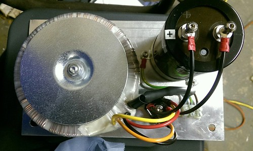
.
One tip here is for connecting up the transformer. As I'm paralleling the outputs, and the bridge rectifier uses faston/spade terminals, I need to get two wires into a suitable crimp. My personal preference is to use uninsulated crimps, and crimp the wires like this-
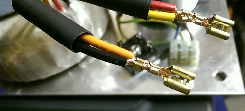
.
Using a single wire, the top of the crimp should crimp the insulation, which gives better support to the wire and reduces the likeliness of the wire snapping due to fatigue, however you won't get the insulation of two wires into this kind of crimp. So the solution-
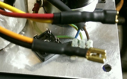
A couple bits of heatshrink. I shrink the first bit on so it only covers the crimps, as per the lower orange/black wires, then put a second bit to act as the insulator for the terminal as per the top red/yellow wires. A single bit would do the job, but I like to provide a bit extra support for the wire.
.
One tip for all crimp terminals, is after you think you've crimped them, try pulling them of the wire. For uninsulated crimp terminals, the wire should snap before you're able to pull the connector off, however insulated crimp terminals, they're more likely to pull out.
For any size of reasonable wire, if you can pull the terminal off just by using your finger and thumb, then they're not crimped tight enough, and likely to give problems later.
.
One thing not visible in the picture, is prior to final assembly the bridge rectifier gets some heat transfer paste put on it improve heat transfer to the aluminium plate, which brings me to the final bit of linear power supplies.
A bridge rectifier also introduces a voltage drop between the input and output, which is why it needs to be attached to some form of heat sink.
I think this one was rated at 1.1V drop at load, so if I was to manage to use the full 15A output of the transformer, I'd be looking at 16.5W of heat needing removed. In free air with no heatsink, the bridge rectifier would quickly be reduced to a smouldering blob.
Now that volt drop also needs to be taken into account for out final output voltage, so in theory with the peak AC voltage of 46.67V, I should get a DC voltage of around 45.5V at the capacitor.
.
Now as I mentioned earlier about theory and real world, using a reasonably accurate multimeter, I get around 52VDC at the capacitor. That's a good 14% higher than our calculated figure. This will drop under load, but it may also rise above that under hard deceleration of motors, which is why you should always allow a reasonable safety margin between your power supply voltage and the maximum allowable stepper driver voltage.Avoiding the rubbish customer service from AluminiumWarehouse since July '13.
-
The Following User Says Thank You to m_c For This Useful Post:

 Reply With Quote
Thread Information
Users Browsing this Thread
There are currently 2 users browsing this thread. (0 members and 2 guests)
Similar Threads
-
Denford Triac - Help
By mikeadams1985 in forum Denford MillsReplies: 1Last Post: 12-01-2017, 10:06 AM -
FOR SALE: Denford Triac CNC PC
By ricey3 in forum Items For SaleReplies: 6Last Post: 10-01-2017, 01:39 PM -
Denford Triac VMC
By fidia in forum Milling Machines, Builds & ConversionsReplies: 6Last Post: 19-08-2016, 08:18 AM -
Help Denford triac p.c.
By mikeulike in forum Denford MillsReplies: 3Last Post: 02-06-2015, 03:59 PM -
WANTED: Denford Triac
By edwardsjc in forum Items WantedReplies: 13Last Post: 20-08-2012, 08:17 AM

Bookmarks