
-
14-11-2016 #1

 Last Activity: 1 Day Ago


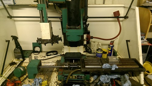
So, after a bit negotiation, this got dropped outside the workshop a few weeks ago -
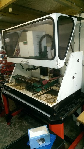
I'd been looking for one for a while, and this one ticked most of the boxes (enclosed, coolant, ATC, autolube). My only complaint is it's a BT35 taper, however it also came with this-
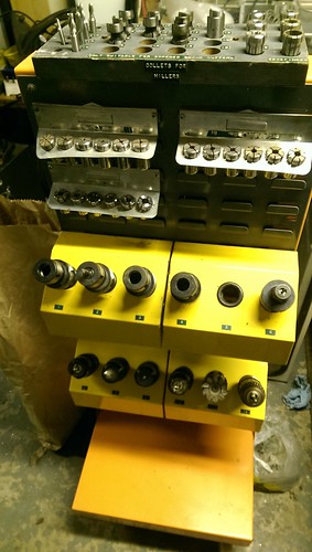
Which should be enough holders to keep me going for a while. I have possibly found a source for new holders, however I'm weighing up the options between buying new holders, or converting it to BT30.
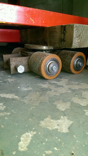
One thing I do have to mention, is a set of machine skates has got to be one of the best things I've built. Made rolling it into place very easy -
I'll gradually add to this thread, but at the current moment, the machine is still partially dismantled, mostly cleaned, and the old controller stripped from the cabinet.Avoiding the rubbish customer service from AluminiumWarehouse since July '13.
-
14-11-2016 #2
Last Activity: 1 Day Ago
Since I'm still waiting for a computer to finish updating, I'll add some more.
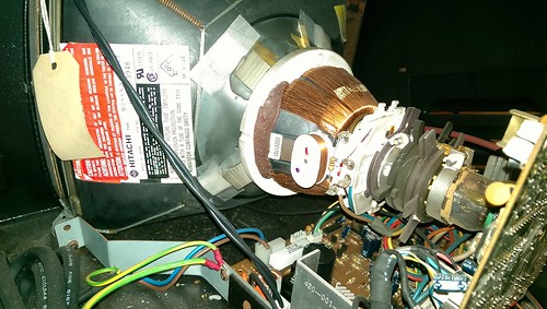
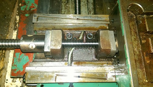
The machine didn't appear to be in the best of condition, however on close inspection all the slides are in excellent condition, they just needed a bit clean. The spindle on the other hand didn't feel so good. Removing the spindle motor didn't improve the feel, so after removing a bit more, the problem became obvious-
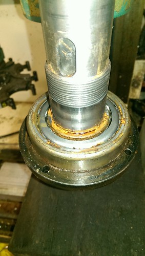
The machine had got wet at some point, as there was rust around the spindle from where water had been sitting, so a couple new bearings, some grease, and the spindle is as good as new.
I still need to decide on the final preload of the bearings, as even the Denford guys say they were just done by feel in the factory.
The other issue, in true education system style, the mill had been used to machine wood. My lathe was the exact same, with dust everywhere, and a nightmare to clean.
 Avoiding the rubbish customer service from AluminiumWarehouse since July '13.
-
15-11-2016 #3
Last Activity: 1 Day Ago
Rather than have this thread as just another "look at what I got/done" thread, I'm wanting to explain some of the reasoning behind the choices.
.
Denford use pretty industrial type setups for their electrics, so all the control electrics in this machine already run 24V, which I'll be sticking with, as 24V controls pretty much eliminates all noise problems. (If there is demand I'll go into the details of the why higher voltage is better)
This particular machine is a VMC version (basically means it comes with inbuilt computer/display/keyboard), running stepper motors courtesy of a parker SD rack.
.
Here's a few pics.
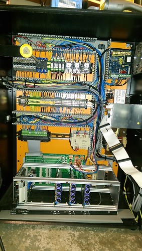
Original control cabinet setup-
.
It powers up!
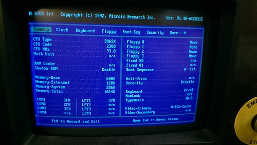
Check the whopping 1024kb of memory and 33MHz clock speed :-)
.
I love old school tech-
.
Now that's how it came. Cutting edge technology for the early nineties, and would likely still work if I could be bothered finding a working floppy disk drive to create a new floppy disk. But I need this machine working, not stuck running archaic software/hardware.
.
In an ideal situation, I'd install servos, however I don't have the budget or time to rework everything to fit servos.
Instead, I'm going to stick with the original steppers for now, and using modern drivers.
I've opted for Leadshine EM806s. A lower end drive would also of worked, but I want to make this machine as reliable as possible, so the stall-detection of the EM drives gives an extra bit protection should something go wrong.Avoiding the rubbish customer service from AluminiumWarehouse since July '13.
-
The Following 3 Users Say Thank You to m_c For This Useful Post:
-
15-11-2016 #4
Last Activity: 1 Day Ago
Now having decided what general direction I wanted to go with the mechanics, it was time to look at controller options. For me personally, I prefer Dynomotion KFlops, as they are probably one of the most versatile controller available for the price, but this left me the problem of deciding what add-on boards were needed.
.
The first thing to consider was what input/output capability was needed.
For this purpose, I create a spreadsheet, and list every input/output I need, along with a note of the type of input/output needed. At the current count it's 28 inputs (2 analogue for SSO&FRO, 1 encoder input for a MPG, with the rest being basic on/offs), and 9 outputs (1 analogue with rest on/offs), along with the currently required 3 step/dir outputs.
.
I could of opted for a KStep board, which would of met the needs for driving stepper motors, albeit at a slightly lower voltage (it has a max Voltage of 50V), but it lacks any kind of analogue input.
.
The other option, was to use a Kanalog. Now this is primarily aimed at retrofits on machines using +/-10V servos, however as I'd like to keep my options open, it provides a good upgrade path. It also has analogue inputs, and differential encoder receivers.
It also so happens I already had a spare one sat on a shelf, along with a Konnect expansion board, which means I've got more inputs and outputs than required.
.
The only draw back was I'd like to make use of the differential inputs on the EM806's, and Dynomotion have nothing that outputs differential step/dir signals. So a solution was needed, and it came in the creation of this board-
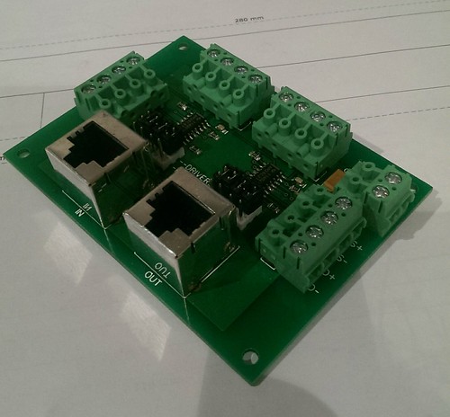
On the KFlop, in standard configuration, the encoder pins also double up as the step/dir pins, of which 8 of them happen to go through a separate RJ45 connection (the other 8 go through one of the ribbon cables). This board takes those 8 lines, and by moving the jumpers, either routes them directly through to the Kanalog to be used as encoder inputs, or to the line driver chips on the board to be used as differential/line driven outputs.
So that was the step/dir differential outputs taken care of.Avoiding the rubbish customer service from AluminiumWarehouse since July '13.
-
15-11-2016 #5
 Last Activity: 1 Day Ago

No plans to do anything like this myself but interesting to see the conversion and the thought processes as it evolves. And that little converter board looks very neat, well done.
-
The Following User Says Thank You to routercnc For This Useful Post:
-
16-11-2016 #6
Last Activity: 1 Day Ago
I was going to post about some of the intricacies of the machine wiring, however I'll stick with controllers for now.
.
Now I've got all the boards, I need to mount them.
The old computer, which was bolted to the control cabinet door was removed, and a suitable bit 3mm aluminium sheet was cut to size. The reason for 3mm, is it's strong enough to bridge pretty big areas with minimal support, and thick enough for drilling/tapping for directly mounting items. Thinner would be marginal for drilling/tapping, and thicker just adds expense for little to no benefit.
.
First step once the sheet had been cut and drilled for mounting to the cabinet door, was to play tetris with the various boards-
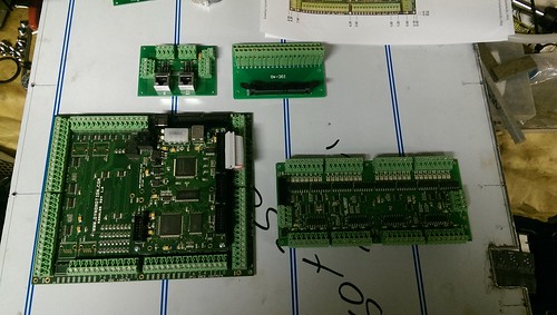
Which highlighted the first non-ideal thing. My lovingly designed and built differential driver board would of been better had the in/out RJ45 jacks been the opposite way around. As it stands, it just means I need to make the cables a bit longer and they'll cross.
If noise was to be a problem, I choose the shielded jacks so shielded cable could be used if needed.
.
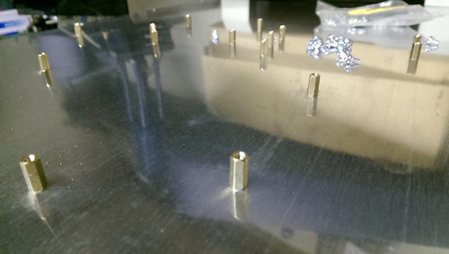
So now things are positioned, it's a case of marking out all the various holes, followed by drilling and tapping all the required holes.
When doing this, is I like to drill the required holes slightly undersized. Everything mounts via M3 stand-offs, and Standard/Course M3 has a pitch of 0.5mm, so the ideal tap drill size is 2.5mm. Instead I use a 2.4 or 2.3mm drill, as it allows a bit margin for if the drill isn't perfectly straight, or isn't drilling perfectly on size.
I then tap using a M3 spiral flute drill in the cordless drill, before hoping my marking out and drilling was on target-
.
Managed to only get one hole slightly off, but thankfully it was for the IDC breakout board, so a quick file and everything bolted together perfectly-
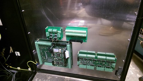
Something I like to do here, is although I fitted all the boards on the bench, I never tightened the screws until I had the plate bolted to the cabinet door. My reasoning for this is to minimise the amount of strain placed on the PCBs should the back plate twist any when finally bolted down.
.
And you may be wondering why the IDC breakout board has been added. I may need to use a couple of the feeds provided by the Kanalogs IDC header, so it's far easier to fit the board and not need it, rather than fitting it later and risk getting some swarf somewhere I really don't want to.Avoiding the rubbish customer service from AluminiumWarehouse since July '13.
-
The Following User Says Thank You to m_c For This Useful Post:
-
17-11-2016 #7
 Last Activity: 4 Days Ago
Thanks m_c, I am finding the reasoning and associated detail that you're providing particularly beneficial for my edification and ultimately future build.
Last Activity: 4 Days Ago
Thanks m_c, I am finding the reasoning and associated detail that you're providing particularly beneficial for my edification and ultimately future build. Originally Posted by m_c

Andy
-
26-11-2016 #8
Last Activity: 1 Day Ago
Next problem was power for the steppers.
After finding a couple datasheets for the fitted stepper motors which listed the motor inductance, a reasonable accurate working voltage could be calculated.
The listed inductance is 3.2mH (milli Henries for those wondering what the H means) for the X and Y motors, and 5.5mH for the Z axis motor.
Now using the calculation courtesy of GeckoDrive's Stepper Motor Basics guide (worth a read for those wanting to know more about steppers and suitable power supplies), which is 32 * vL = VMAX.
L is the Inductance, and the little v is meant to be a square root symbol, so after a bid BODMAS I.e. work out the root before doing the multiplication, we get a max voltage of 57.24V for X and Y, and 75V for the Z.
.
The original Parker SD rack ran of a transformer outputting +44,+18,0,-18 & -44V.
For those unfamiliar with how AC voltage is measured, it is commonly measured as RMS (Root Mean Square - google it if you really want to know the detail!) voltage, which in a very simplistic way can be considered the average voltage.
Taking a 44VAC voltage, in an ideal world, the peak voltage would be 44 times the square root of 2 (RMS nicely works out as root 2, or 1.414), which gives us 62V.
Off course, in the real world, that voltage will be higher. Due to mains voltage fluctuations (can be as high as 10%), and the fact the transformer voltages are at rated load meaning due to internal losses the unloaded voltage is higher (if you see voltage regulation figure for a transformer, this is what it relates to), you can end up with a peak voltage far higher than calculations.
.
However, the original transformer is marginally small to make full use of the steppers. No official ratings could be found for it, but going by a rough guestimate of it's physical size, I'd put it around the 2-300VA size, which was perfectly adequate for the original drives, running 2A on the X and Y, and 3A on the Z. Plus there would be the problem the outputs are split between positive and negative, meaning I would have to in effect create two separate linear supplies to make full use of the transformers capability.
.
So, a new supply was needed.
After a running a few calcs on commonly available toroidal voltages, I picked a 500VA 33VAC.
Given this is a mill, where every last ounce of performance is not needed (voltage only limits maximum speed), I decided somewhere around 50V would do fine. Combine that with running modern drives, and higher current, performance will be greatly increased anyway.
The 33VAC should in theory give me a peak voltage of 46.67V, and by using a higher rated transformer (a 300VA would most likely work good enough) there will be less voltage drop under load.
.
Once again, I took a bit aluminium plate, arranged a few bits, drilled some holes, and added some bit wires, to end up with this-
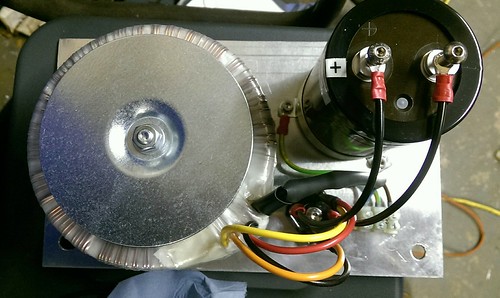
.
One tip here is for connecting up the transformer. As I'm paralleling the outputs, and the bridge rectifier uses faston/spade terminals, I need to get two wires into a suitable crimp. My personal preference is to use uninsulated crimps, and crimp the wires like this-
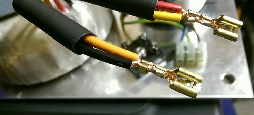
.
Using a single wire, the top of the crimp should crimp the insulation, which gives better support to the wire and reduces the likeliness of the wire snapping due to fatigue, however you won't get the insulation of two wires into this kind of crimp. So the solution-
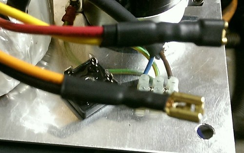
A couple bits of heatshrink. I shrink the first bit on so it only covers the crimps, as per the lower orange/black wires, then put a second bit to act as the insulator for the terminal as per the top red/yellow wires. A single bit would do the job, but I like to provide a bit extra support for the wire.
.
One tip for all crimp terminals, is after you think you've crimped them, try pulling them of the wire. For uninsulated crimp terminals, the wire should snap before you're able to pull the connector off, however insulated crimp terminals, they're more likely to pull out.
For any size of reasonable wire, if you can pull the terminal off just by using your finger and thumb, then they're not crimped tight enough, and likely to give problems later.
.
One thing not visible in the picture, is prior to final assembly the bridge rectifier gets some heat transfer paste put on it improve heat transfer to the aluminium plate, which brings me to the final bit of linear power supplies.
A bridge rectifier also introduces a voltage drop between the input and output, which is why it needs to be attached to some form of heat sink.
I think this one was rated at 1.1V drop at load, so if I was to manage to use the full 15A output of the transformer, I'd be looking at 16.5W of heat needing removed. In free air with no heatsink, the bridge rectifier would quickly be reduced to a smouldering blob.
Now that volt drop also needs to be taken into account for out final output voltage, so in theory with the peak AC voltage of 46.67V, I should get a DC voltage of around 45.5V at the capacitor.
.
Now as I mentioned earlier about theory and real world, using a reasonably accurate multimeter, I get around 52VDC at the capacitor. That's a good 14% higher than our calculated figure. This will drop under load, but it may also rise above that under hard deceleration of motors, which is why you should always allow a reasonable safety margin between your power supply voltage and the maximum allowable stepper driver voltage.Avoiding the rubbish customer service from AluminiumWarehouse since July '13.
-
The Following User Says Thank You to m_c For This Useful Post:
-
26-11-2016 #9
Last Activity: 1 Day Ago
Wiring. Lots and lots of wiring.
And how do you wire a retrofit?
.
Thankfully, Denford are quite happy to make available what wiring diagrams they have for older machines. Their forum (www.denfordata.com) contains lots of information, and also a few different sets of wiring diagrams for Triac's, and having already retrofitted a Cyclone lathe, I've learnt a good bit about how they do things.
.
The first problem I knew I had to deal with was the homing sensors. Denford use NAMUR output sensors, which are a two wire sensor aimed at explosion risk applications. It has been asked on the Denford forum why they were chosen, but none of the current employees know.
They could be made to work, either through some expensive NAMUR barrier interfaces, cutting the old control board up to get the required circuit, or playing around with opamps, resistors and transistors, but swapping them out for new 3 wire sensors makes far more sense.
.
Until you realise where the wiring runs for the X-axis sensor and limit switches, and the existing 4 core cable needs an extra core. All the X-axis switches sit at the front of the table underneath the front bellows, and upon initial inspection, I thought the wiring passed down through the front of table, and I was looking at a major strip down job to run new wiring.
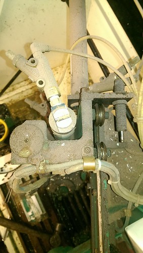
After a bit studying of parts diagrams, a good bit umming and arring, a start was made, with me expecting to need to remove the complete Y assembly from the mill, and possibly even the mill from the enclosure. However, after reaching this point-
A deep breath of relief was had, upon realising the wire simply passed over the top of the assembly, before going down through a hole and being cable tied to the autolube pipes underneath the base-
With some use of various pliers, side cutters, and skin removal, I managed to get the old cable removed, and a new cable fed in. For the new cable, I opted for some high oil resistance chainflex cable from Igus (CF9.02.06 to be precise), which is a similar diameter to the old cable, but with 6 cores.
Something to consider when carrying out a retrofit, is the condition of the original wiring. Although this cable was still functional, underneath the table, the wire had gone brittle, so it would of likely failed at some point fairly soon. Spending a bit extra time during the retrofit to check things can save you lots of unplanned grief later.
.
Now the biggest wiring headache on the machine has been dealt with, and the main new bits are mounted in the cabinet, it 'just' leaves this to sort out-
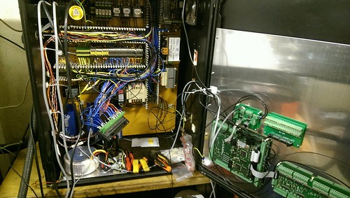 Avoiding the rubbish customer service from AluminiumWarehouse since July '13.
-
The Following User Says Thank You to m_c For This Useful Post:
-
04-12-2016 #10
Last Activity: 1 Day Ago
Wires. Wires. Wires everywhere.
.
.
So where do you start with wiring a retrofit?
For me it's always the power supplies, and related circuitry.
First up was a switched mode 5V DIN rail mounted PSU to power the KFlop/Kanalog. Nice and simple, it gets a permanent live feed whenever the machine is switched on. It can just be seen on the lower DIN rail just to the left of the original cream coloured 24V supply.
.
Next is the big linear supply for the steppers, however it relies on being controlled by the E-stop circuit. As is best practise when powering stepper drivers, you only ever switch the input side, so a suitable contactor was added, controlled via the E-stop circuit, which is at the very left of the lower DIN rail.
Something I struggled with while initially deciding on how to handle E-stops and enabling on earlier retrofits, was what should be hardware controlled, and what should be software controlled. The advice I got, was keep them distinctly separate. Two main reasons for this, first is it avoids a race situation, and two, should something go wrong, you should know if it's due to a hardware or software problem.
For those not familiar with a race situation, it's more a programming term, where due to two interdependent conditions, they both get stuck because of each other.
In terms of what I'm discussing here, if you were to rely on the control/software activating the E-stop circuit, how would you initially activate it, given the control would see it as tripped due to the fact the control hasn't activated it?
.
This is where drive enable circuits come in.
The E-stop circuit cutting power should be seen as a final way to kill motion in the event of controller failure, as it will usually take a second or two for the power to drop low enough for motion to stop.
By using the enable signal to stop motion, motion should stop quicker, although by removing the enable, the motor will usually be left to freewheel to a stop. However on a stepper driven machine this is not usually a major issue.
Off course, as I'm using a KFlop, this gives me the ability to handle this aspect however I like. This gives me the option to implement a minor delay between stopping the step/dir pulse stream, prior to the enable signal being removed.
I end up with a flow like this-
1) E-stop circuit deactivated (I.e. E-stop button pressed, limit switch hit)
2) Power disabled and KFlop notified E-stop triggered simultaneously
3) KFlop immediately stops motion signals
4) 200ms later KFlop removes enables
5) Residual power drains
.
You may be wondering why I'm happy to rely on the KFlop in this way, but it's because it will do exactly what it's programmed to do. It's not like a PC which may hang due to myriad of things. At this level of operation, it's programmed as a microcontroller, with no influence from the PC. Once the system has been initialised, you can unplug the PC, and the KFlop will still react in the same way. Even if it wasn't, the removal of power will still stop motion eventually.
.
Off course, once you get into servo drives, you have other considerations, like do you really want to cut power instantly (cutting power will usually result in drives faulting and motors freewheeling to a halt), servo drives usually have the option of implementing a Stop signal, which when triggered will cause the drive to stop the motor as fast as possible.
.
The only addition I did make to the original E-stop circuit, was the Kanalog board has an enable signal, which goes active once the KFlop and Kanalog board have fully powered on. The reason for this, is during initial power up, prior to the KFlop establishing communication with the Kanalog board, the Kanalog outputs will be in an indeterminate state (i.e. they are not guaranteed to remain deactivated). I simply use the signal, which is a relay driver capable output, to power a relay, which in turn is part of the E-stop circuit. For those familiar with parallel ports/Mach/LinuxCNC, it can be thought of as a charge pump circuit.Avoiding the rubbish customer service from AluminiumWarehouse since July '13.
-
The Following User Says Thank You to m_c For This Useful Post:

 Reply With Quote
Thread Information
Users Browsing this Thread
There are currently 1 users browsing this thread. (0 members and 1 guests)
Similar Threads
-
Denford Triac - Help
By mikeadams1985 in forum Denford MillsReplies: 1Last Post: 12-01-2017, 10:06 AM -
FOR SALE: Denford Triac CNC PC
By ricey3 in forum Items For SaleReplies: 6Last Post: 10-01-2017, 01:39 PM -
Denford Triac VMC
By fidia in forum Milling Machines, Builds & ConversionsReplies: 6Last Post: 19-08-2016, 08:18 AM -
Help Denford triac p.c.
By mikeulike in forum Denford MillsReplies: 3Last Post: 02-06-2015, 03:59 PM -
WANTED: Denford Triac
By edwardsjc in forum Items WantedReplies: 13Last Post: 20-08-2012, 08:17 AM

Bookmarks