
Hybrid View


-
11-08-2017 #1

 Last Activity: 2 Weeks Ago


Hi all, this is the first post of my build log.
After reading a lot on this site i made some of the build decisions.
Basically it is a half raised gantry router.
Planning on 15mm alu toolingplate Z-Axis
1st.. size.
- 1500x 800 x 200 mm work area.
2nd materials to be cut.
- Wood and aluminium.
3rd basic building material.
- Steel box section. 120×80×4mm and 80x80x4mm
Router type.
- 4 bearing Chinese WC ER20 2..2kw
VFD ...
-Danfoss FC-51 type.
linear stuff.
- 20mm rail, c7 rolled ballscrew1610 for Y, 1605 for Z, 2010 for X
- 4 x nema 23 3 or 4 NM type
Or maybe 2 nema23 and 1 nema 34...
Is undecided for now.
Tools
-I have no access to mill.
-I have access to old lathe. but no real experience
- Basic hand / power tools.
- Design sw
Solidworks.
Cnc controls
- Eyeballing uccnc300eth
- Digital drivers 68v diy psu
So that is the plan.
I do notice i am refining the plan on the go.
Verstuurd vanaf mijn SM-A320FL met TapatalkLast edited by driftspin; 11-12-2017 at 12:19 AM.
-
11-08-2017 #2
 Last Activity: 20-04-2020
Hello!
Sounds awsome :D
Good luck and for ours sake post a lot of pictures..!
Skickat från min SM-N910C via Tapatalk
-
11-08-2017 #3
Last Activity: 2 Weeks Ago
Yes... pictures... ill try to post on every progress..
 Originally Posted by Nr1madman

Actually i started work on a design over a year ago.
1st the plan was to make an adjustable bed.
This over complicated the design.... or weakened it...
now the design is more basic.
Verstuurd vanaf mijn SM-A320FL met TapatalkLast edited by driftspin; 11-08-2017 at 07:55 PM. Reason: Pictures added
-
11-08-2017 #4
Last Activity: 2 Weeks Ago
Buying steel is not a problem.
Getting 6mtr length box section cut or stored in my shed is..
Shed is just 5.7m X 3.7m
So i orderd the steel box section, and some end plates pre cut, ready to weld up.
A friend of mine works with steel, he is my main supplier for steel related stuff.
We share a hobby 150 Amp migwelder. (Cebora)
It was bought for automotive related welding.
-
11-08-2017 #5
Last Activity: 2 Weeks Ago
This is what the start of my cnc hobby looked like in the back of my car
I spirit levelled the top of a standard used desk for setting up the bed box section.
Dont ask me why i did not start with the legs of the frame.
Ok .... its gonna be bulky...
Tag welding it up
After final welding i found out warping will happen...
Total distortion is now +/- 1.5 mm
1850x1160 mm total size.
I have read on this forum this could happen... But is was still more than i expected.
Epoxy has to solve this problem in a later stage...
More to come.
Verstuurd vanaf mijn SM-A320FL met TapatalkLast edited by driftspin; 14-09-2017 at 07:11 PM.
-
11-08-2017 #6
 Last Activity: 1 Hour Ago


 I would re think this for me I would use 1610 for X & Y and 1605 for Zlinear stuff.
- 20mm rail, c7 rolled ballscrew1610 for Y,Z, 2010 for X
- 4 x nema 23 3 or 4 NM type
Or maybe 2 nema23 and 1 nema 34...
Is undecided for now.
With nema 23 3.1nM
Have a look a Joe's build http://www.mycncuk.com/threads/4513-...ight=joeharris..Clive
The more you know, The better you know, How little you know
-
11-08-2017 #7
Last Activity: 13-07-2023

looks nice, I'd just be a little concerned about how you are going to make the rails work on the gantry? That orientation is going to be very tricky to align within the required tolerances on a steel beam. What was your plan in that regard?
-
12-08-2017 #8
Last Activity: 2 Weeks Ago
Dear Zeeflyboy, Originally Posted by Zeeflyboy
I hope for a miracle by epoxy
First one needs a zero reference for horizontal level.
I think it was Boyan who explained on the forum he made a reference level surface for this on a concrete floor by pouring epoxy.
I will try this way.
I will spirit level and anker bolt my frame to the concrete floor before pourings so nothing can move and use the x poured epoxy rail mounting surface for this.
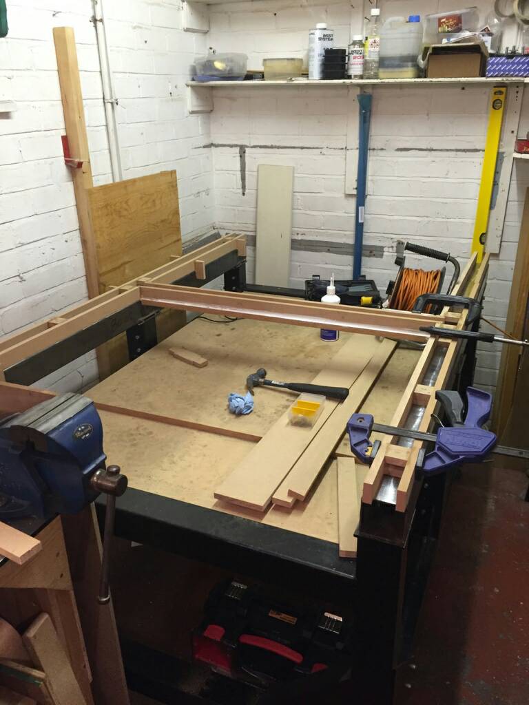
Pouring the rail mounting surface for X will be done like the example from a forum member see picture.
like the X axis the 4 mounting surfaces on the gantry will be epoxy levelled.
In 2 steps...
Step 1 I will do the 2 gantry X rail carriage mounting surfaces, and bottom Y rail mounting surface pouring, in 1 go. ( gantry upside down )
There will be an epoxy levelling bridge between the 2 carriage mounting surfaces
Similar to x rail pouring setup
So now those 3 surfaces will be in the same plain.
After curing..
Step 2 The gantry can now be flipped to normal position and top Y axis rail mounting surface can be poured..
Placing the gantry in the normal position on the mounting surface of the x rail should give the best possible reference for a level plain.
After pouring Y bottom and top should be in the same plain..
In theory this should work.
I know this will be a critical process.
When this method fails i will redesign and have the gantry (rail) mounting surfaces milled. nothing much changes only a few pounds of steel added.
When milling is needed i will upgrade the gantry box section to 80x120x8 or 10 to have some meat to mill
I do want to avoid **bolting** the gantry sides to the gantry Y-axis.
I prefer welded solid for best rigidity.
But welding solid must be avoided going that route, because of warping.
I have no friends with a mill capable of box section 1200X120x80.
Would a surface grinder work for this purpose?
Any other thoughts?
Verstuurd vanaf mijn SM-A320FL met Tapatalk
-
12-08-2017 #9

 Last Activity: 3 Days Ago
Thats how i did it on the gantry, my first build. gantry was flipped 180 degree and i poured gantry sides and lower beam epoxy. Then flipped and did upper rail. No problem.
But you will need a straight edge and 2 precision squares for later when mounting the rails and so...
-
14-08-2017 #10
Last Activity: 13-07-2023
Sounds good! Will watch with interest. Good luck! Originally Posted by driftspin
Last edited by Zeeflyboy; 14-08-2017 at 12:33 PM.

 Reply With Quote
Thread Information
Users Browsing this Thread
There are currently 1 users browsing this thread. (0 members and 1 guests)
Similar Threads
-
BUILD LOG: First time build - Steel Frame CNC Router
By examorph in forum DIY Router Build LogsReplies: 144Last Post: 19-10-2023, 06:25 PM -
BUILD LOG: First Build 5 x 12 Steel Frame CNC router
By Scott Damman in forum DIY Router Build LogsReplies: 104Last Post: 18-01-2017, 06:36 PM -
BUILD LOG: Steel frame cnc router design/build
By CraftyGeek in forum DIY Router Build LogsReplies: 110Last Post: 06-05-2015, 10:00 PM -
600x900 Steel welded router build
By embraced in forum Gantry/Router Machines & BuildingReplies: 7Last Post: 08-10-2014, 10:55 PM -
BUILD LOG: First steel diy CNC router build
By ivars211 in forum DIY Router Build LogsReplies: 59Last Post: 28-07-2014, 08:29 PM

Bookmarks