
Thread: Siff' Build Log
-
18-07-2011 #1

 Last Activity: 09-02-2012


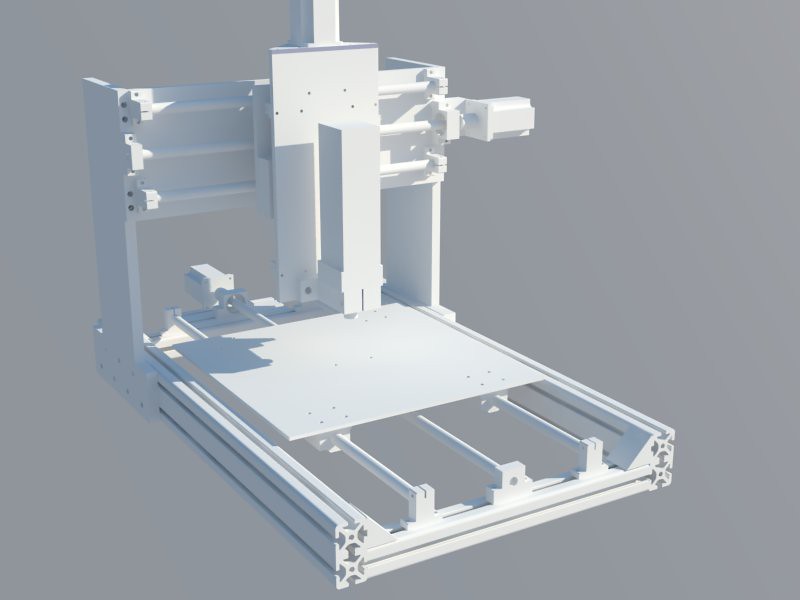
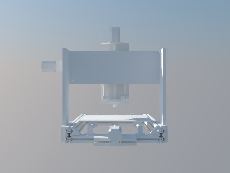
Hi guys, below are some images and renders of my first proposed CNC machine. I intend to do a small amount of aluminium and wax routing, but mostly I intend to use this to aid in the manufacture of speaker cabinets and PCB milling.
I've just posted an RFQ over in the other forum asking for quotations on getting some of the parts made up.
Cutting area is 400mm x 400mm and the parts I intend to use include:
Ballscrews all around
Kress 1050-1 FME
Valuframe extrusion
Gecko 540 stepper driver
For the stepper motors i'm not sure, but I was looking at these: http://cgi.ebay.co.uk/3-Stepper-Moto...7#ht_535wt_911. If I understand correctly, even though the motors require 4.2A and the gecko only provides 3.5A, this would mean that the motors just run at reduced torque, and wouldn't damage them, or the controller. Please correct me if i'm wrong.
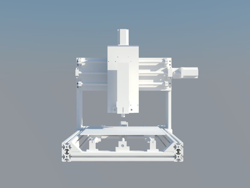
The only thing I don't like about the design is how far the Y axis stepper motor sticks out. I was originally looking at setting the motor in the upright support and using a timing belt/pulley combo, but i'm not sure i'm willing to deal with the extra cost and potential increased backlash for the sake of aesthetics.
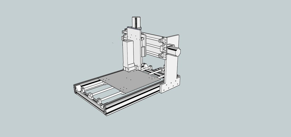
7 by SgtSiff, on Flickr
4 by SgtSiff, on Flickr
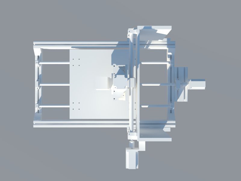
3 by SgtSiff, on Flickr
2 by SgtSiff, on Flickr
1 by SgtSiff, on Flickr
5 by SgtSiff, on Flickr
Thanks for looking.
-
20-07-2011 #2
Last Activity: 22-12-2013

Looks good but I am sure you will regret using unsupported rails. Changing to supported rails will give a much stronger and more accurate machine.
-
20-07-2011 #3
 Last Activity: 08-09-2018

Unsupported will be fine as long as you make them thicker. I would suggest turning the Y frame around 180 degrease as well to centre the weight more and you could then shorten the bed/ rails. You could always mount the Y motor around the back and use a small belt 1:1 to power it as well to stop it sticking out?
If the nagging gets really bad......Get a bigger shed:naughty:
-
20-07-2011 #4
 Last Activity: 2 Days Ago

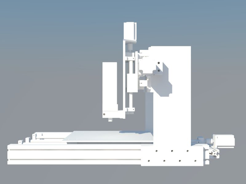
Oh dear. Suggest you redesign it a bit and do everything possible to get rid of the overhangs. You really want the shortest possible connection between the router bit and the workpiece to minimise flex. Do you really need that much travel on the Z?
Flex is easy to overcome, you simply reduce the cut depth/feed. If you want to cut deep and hard fix it now before it's all too late :naughty:
-
21-07-2011 #5
 Last Activity: 05-04-2020
 That is correct. You could always run them in bipolar series ... then you only need 2.1A. That will reduce the torque slightly at higher speed than with parallel, but I'm pretty sure it will be less of a loss than using only 83% of the rated current. The power dissipation of the motors will be about 70% of rated running on 3.5A. Why gecko? Something like PM752 or PM542 on from eBay or Zapp should be cheaper and will let you run at the full current and (with PM752) higher voltage.
 Originally Posted by everyreasonto

I agree unsupported rail is a bad plan, especially on the X-axis as the end fixity is poor. Even 30mm unsupported rail will flex more than 12mm supported. Granted the load ratings of the bearings on the 30mm rail would be higher but they're plenty more than required anyway. I would use 16mm, or more if you can afford it. 25mm supported rails are good as they have an additional row of balls ... though on this size of machine you don't need that size. Have you looked on eBay for them? They're cheap from linearmotionbearings2008.
You might want to bolt the Y axis plate to the back of the gantry, not the front, as that will get the centre of mass closer to being half way between the pairs of X-axis bearings.
There is a lot of overhang, as Robin said do you really need that much Z travel? If so you're best to eliminate the gantry sides altogether, like I did here:
Plate is also the worst profile for the gantry sides since it bends easily in the direction parallel to the Y-axis, however you've compensated for that by having a plate parallel to the Y axis, so the only thing it will lack is torsional stiffness. You could use something lighter if you changed the cross section - maybe extrusion? That's expensive though. Steel box section is cheap and the weight isn't really an issue since the gantry is fixed. Just make it as strong as you can.
Also if you want the machine to be fast use timing belts on the stepper motors/screws to get the motor operating in the right region. Since you're machine is quite light you will almost certainly want the pulley on the stepper motor to be bigger than on the screw. What pitch ballscrews are you using, probably 5mm? I have not noticed increased backlash from using timing belts/pulleys. They do stretch very slightly, but I don't think that's a big issue.
Nice drawing ... if you do decide to use supported rails I can send you the drawings I did of them to save you a bit of time if you like...Last edited by Jonathan; 21-07-2011 at 11:25 AM.
-
22-07-2011 #6
Last Activity: 09-02-2012
Thanks for the input guys, I really appreciate it. I hadn't seen the seller linearmotionbearings before.. boy is he cheap! I'm really liking the look of the machine you posted Jonathan but wouldn't I need two ballscrews and two steppers on the X axis?. looks like I could get a larger machine for the same budget, using the supported rails that everyone seems to be suggesting from linearmotionbearings. The rails I put in the original plan were 16mm so I guess I overestimated their strength.
Budget is my only constraint, excluding spindle, I have about £1000 to spend.
Taking advice on the stepper drivers, I've found some from a seller called cnc4you. I also intend to get my steppers and ballscrews from there.
EDIT: Looks like i'm going to go for this set: http://www.ebay.co.uk/itm/3-SBR20-se...#ht_1004wt_948. Would work out around £450 shipped (inc tax) and they are all 20mm rails.
It would fit very nicely to the 60x30 profile from hepcomotion.
I'm going to make a point of avoiding Valuframe extrusion because they said that delivery would be £33 + VAT if they were sending to a private address, robbing gits!Last edited by everyreasonto; 22-07-2011 at 01:17 AM.
-
22-07-2011 #7
Last Activity: 05-04-2020
When you've decided what lengths of ballscrew and rail you want send him a message with the sizes and he will list them on eBay. Originally Posted by everyreasonto
Yes you would - it's the best way to do it anyway. You could link the two ballscrews with a timing belt and just use one stepper motor. Another way is to use cables beneath the gantry (like on a drawing board ruler) to link the two sides... Originally Posted by everyreasonto
There's more about it in my build log, probably just read the last few pages!
http://www.mycncuk.com/forums/showth...outer-building...
Also here for more pictures, though this isn't neccecary for the size of your machine.
http://www.mycncuk.com/forums/showth...t-design-ideas
£1000 not including spindle should be plenty...less than I spent. Originally Posted by everyreasonto
Get your ballscrews from linearmotionbearings. They will be exactly the same and end machining is very very cheap. Look on eBay for stepper drivers - there's some 80V ones that look tempting, or if not this is what I got because at the time they were not on eBay cheaper:
http://www.zappautomation.co.uk/pm75...71a69c8def8e2f
I also used the 3nm motors...
I think steel box section is much more cost effective than using extrusion. Definitely for the stationary parts where weight isn't an issue.
There's a pdf with all the drawings for the ballscrews/blocks etc in one place here ...
http://www.file-vault.us/pdfs/ball_s...umentation.pdf
-
22-07-2011 #8
Last Activity: 22-12-2013
My router was built with rails, bearings and balls crews from linearmotionbearings. The cutting area is 500 x 600mm and the whole build came in at about £1000. I did what Jonathan has suggested and built it from mild steel box section.
Here is a link to the build thread, it may give you some ideas http://www.mycncuk.com/forums/showth...-framed-router
Good luck with the build.
-
25-07-2011 #9
Last Activity: 09-02-2012

Hi guys, this is my latest design. It is based off of Jonathan's design and uses:
15mm plate
20mm supported rails
twin x axis ballscrew
Aluminium extrusion for x axis rail support and Y axis.
Will be welded to an aluminium frame when complete
Let me know if you guys think this is an improvement. The Z axis isn't completely finished yet..
-
25-07-2011 #10
Last Activity: 05-04-2020
Why aluminium? Will be interested to see it welded ... Originally Posted by everyreasonto
Good, as it wont work like that! Originally Posted by everyreasonto
Y-axis: You need to have the 4 plates that make up the 'box' round the linear bearings configured such that the plates with the bearings on can be adjusted to get the bearings precisely parallel. Look how I did it ... just don't copy my mistake - making two of the plates 10mm too short! At the moment it relies on the two plates in the YZ plane being machined very very accurately which just isn't going to happen.
X-axis: End supports for the ballscrews look a bit bendy? Remember that all the cutting force in the X direction will be resisted by those plates, so they want to be strong to stop the tool deflecting much. That's why I made mine the odd looking shape out of bar. The easiest solution I can think of is to replace them with box section then put a smaller plate/disc on that to mount the bearing. Have the holes slotted on both so you can align the ballscrews.
If you rotate the ballnuts by 90° you can get the ballscrews slightly closer to the tool...probably not significant.
The way your Y-axis box section is mounted to the X-axis is a bit bendy as the vertical plates only have a line contact with the X-axis bearings. That's why I used box section...
You could get the gantry even further down? Debatable if it's worthwhile.
Other than that looks good (but obviously I'm going to say that as you copied mine )
)

 Reply With Quote
Thread Information
Users Browsing this Thread
There are currently 1 users browsing this thread. (0 members and 1 guests)
Similar Threads
-
BUILD LOG: New Build - For Your Amusement - MK-2 build
By Karl in forum DIY Router Build LogsReplies: 12Last Post: 08-02-2017, 08:03 PM

Bookmarks