
Thread: DIY spindle design
-
10-12-2008 #11

 Last Activity: 04-01-2011


Sorry I must have misunderstood what you meant by:
"I also wanted a fair degree of accuracy, without the fairly horrid run-out that Dremel-like tools have, as I'd like to try using it for milling PCB's as well."
Phil
-
10-12-2008 #12
 Last Activity: 28-10-2019
Quite a few PCB routers have been built that work fine with small tools like the Dremel, so my aim was to make something that would be a bit better than this, a bit quieter and hopefully have bearings that would last a bit longer, for around the same price.
I've got a couple of Dremels and the newer one seems to have around 2 thou or so of combined run out and play in the spindle, the older one is quite a bit worse. Their real problem seems to be the eccentricity in the collets, as the tool run out is significantly worse than the spindle - to get the best out of them means re-seating the collet several times to true up the tool. Despite this poor accuracy, many people have shown that they work fine for modest PCB milling, such as the homebrew stuff I'll want to do.
The very best I could hope for using ER type collets is about 1/4 thou TIR, assuming no other error sources, as that's their spec. A 1/10 thou TIR would be totally unachievable using this type of collet chuck, I'd have needed to go for something far more costly if that was my aim.
It's debatable as to whether better than a thou is needed for such an application as DIY PCB milling anyway. Minimum track width is unlikely to be less than about 15 thou and assymetric cutter tip loading isn't an issue for a single flute vee tip PCB milling tool. Given that so many people are very successfuly milling out boards with spindles that are far worse than mine is likely to be I really can't see me having a real problem, apart from the slow speed .
This spindle might be a bit too slow for PCB work with small diameter tools, as it will be limited to around 16,000 rpm. It will be ideal for the bigger mould making requirements I have, using tools up to around 6mm or so, so I may just try it for a while with that task, see how it goes, then look at making a faster spindle for PCB work if I need it.
I've found a source for an ER25 chuck with a 1/2" shaft that looks promising for a future higher speed version. Reducing the shaft size from 20mm to 1/2" gives the possibility of using bearings with a higher speed rating, which will allow me to get up to the 25,000 to 30,000 rpm (or higher) that would be best for the PCB task.
It's good fun experimenting anyway, even if I do get one or two failures along the way.
Jeremy
-
14-12-2008 #13
Last Activity: 28-10-2019
I finished the mechanical part of the spindle today and gave it a test run. All went well, but I need to pull it apart and take a tiny skim from the lower bearing housing, as the lower bearing gets a bit warm after a few minutes running. I noticed that the spindle was a little tight after I assembled it. I hadn't realised how a tiny bit of "pinch" from a bearing pressed into a housing that was very slightly undersized would make such a difference, but it's easy enough to fix.
The good news is that the spindle is reasonably quiet and seems to work well off load. The RC motor didn't even get slightly warm, but the speed controller may need mounting on an additional heatsink, as it was a bit warm after a few minutes running. The motor was drawing around 10 amps from a 12V supply when running flat out, which is a bit high and almost certainly to do with the overly tight lower bearing.
I may also need to adjust the bearing pre-load. I've used a couple of belleville washers under the upper shaft retainer, abutting the top bearing inner race. Pre-load was set by clamping the shaft to compress the bellevilles a small amount, then tightening the shaft collar at the lower end. This wasn't very "scientific", so may also be a contributing factor to the warm running lower bearing.
Here's a picture of the completed spindle:
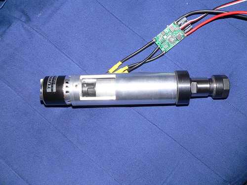
The body is 1.5" in diameter and the overall length is 8.75". The motor outer can at the top (the black bit with the writing on) rotates, so probably needs some sort of guard. The small lovejoy coupling seems to work fine, there's no real vibration at all with it spinning at full chat whilst just being hand-held. Overall it seems to vibrate a lot less than a Dremel and is certainly a lot quieter.
I've done a crude run-out check using a DTI, with it clamped in vee blocks on the surface table. A 3mm carbide cutter shank didn't seem to deflect the DTI at all, which seems pretty good. My DTI isn't really sensitive enough to show anything under about 1/4 thou though, plus the lower bearing is still a bit too tight, so the true run out might be a bit worse.
Nevertheless, if I can fix the lower bearing problem I think I shall be well pleased with this little experiment. Let's hope that the motor turns out to be reliable!
Jeremy
-
14-12-2008 #14

 Last Activity: 57 Minutes Ago


Really nice job mate, have you got any pics or movies of it working ?
.Me
-
14-12-2008 #15
Last Activity: 28-10-2019
Thanks, Lee. I'll try and see if I can take some video of it running after I've fixed the lower bearing problem, as long as I can work out how to get the camera to shoot video! (I know it can do it, but will have to sort out how to get Quicktime changed to avi or mpg, I think!).
Jeremy
-
21-12-2008 #16
Last Activity: 28-10-2019
No videos yet, but I do have an update. During bench testing I found that the motor electronic speed controller was getting pretty warm at mid-range speeds. It was fine when flat out, but would get too hot to touch after 20 to 30 seconds at mid-range. I tried fitting a heatsink to it, but there was clearly something not quite right.
After enquiring on an electric vehicle forum (my interest in CNC is to build EV parts) a couple of the more experienced RC model motor guys suggested I needed to derate the controller to a greater degree if it was to deliver higher power at mid-speed. This makes sense, as a model aircraft propeller absorbs power in proportion to the cube of it's rpm, so the controller wouldn't be optimised for running at high currents at part throttle.
I thought I'd been conservative in buying a 40 amp controller when the most my power supply can put out is 30 amps, but it seems that I was wrong. I've switched to a spare 120 amp controller I have for another project and the performance has been transformed. Not only does the controller not get warm, but the speed control is very smooth indeed and the motor starts from a standstill very well. The other plus point is that the motor no-load current has reduced by about 50%, which goes to show how inefficient the original controller was.
Although the motor whines a bit at max speed (around 16,000 rpm) it's not excessively loud. I've been testing it in my study and have so far not elicited any complaints from SWMBO, which would not be the case if I fired up a router in here!
I've still got a bit of fettling to do, including reducing the drag on the bottom bearing, but all told I'm exceptionally pleased with the outcome so far. It looks like it will meet my design goals of being compact, relatively quiet, affordable and fairly accurate.
Jeremy
-
22-12-2008 #17
Last Activity: 28-10-2019
Hi Kip,
Thanks for the kind words, I just need to crack on with the rest of it now!
The cut out in the housing is to allow the Lovejoy coupling to be connected and also to allow the top collar, that retains the spindle in the housing, to be secured. These both have screws that are inserted from the side to lock them in place, with those for the spindle collar being threaded into the spindle itself.
You can buy some brushless motors from UK model shops, but they are much more expensive than direct from Hobby City in China. My experience with using some of these motors is that the really cheap ones are under-rated and not very efficient, but the mid-range ones are surprisingly good, often not much less efficient or less well made than the really expensive ones.
The key is knowing what to buy. The motors are rated in terms of maximum power (in watts) and also Kv, which is the rpm per volt. This latter figure is important, as it allows the use of a motor that will run at the right sort of speed for the application. In general, it seems that using a high Kv motor and then gearing it down with a reduction belt drive is probably a better way to go, as it reduces the low speed torque requirement from the motor. One of the regular contributors on the Ev forum I frequent has converted his Taig Mill to run on an RC brushless motor (his name is Matt Schumaker and he has a web site here: http://www.recumbents.com/WISIL/shumaker/default.htm with some details of his mill conversion, towards the bottom of the page). Matt gave me some advice on motors and controllers recently, quote:
"Jeremy,
I am running a small outrunner on my CNC too. I have over 100 hours on it so far without any issues. I am running a Castle Creations Phoenix35 ESC on it from a 24 volt, 20 amp power supply.
The issue I think you are having is more a matter of the controller than the motor. Also, I am running a belt drive rather than direct drive. For aluminum cutting, I run it 3 to 1 reduction. For carbon fiber cutting I am running 1 to 1.3 overdrive. This gives me 13,000 RPM at the spindle. My Taig spindle uses huge bearings (maybe 1 and 1/2 inch OD). Yet, my ESC runs fine even driving those huge bearings at such a high speed.
You may be having problems partly because of the low motor RPM as well.
A Castle Creations 35 or 45 amp ESC is relatively innexpensive. I would go that route.
Matt"
A look around the Hobby City site will soon give you an idea as to what's available. The controller that didn't work well for me was one of their very cheap 40A SuperSimple series ( see here: http://www.hobbycity.com/hobbycity/s...Simple_40A_ESC ). Maybe I shouldn't be surprised that it didn't work well, as it cost less than $12.....
The controller I have that works well is a complete over kill, as it's rated at 120 amps continuous, 130 amps peak. It's also less than ideal as it is a relatively high voltage unit (30 volts max) and so doesn't have a built in 5 volt regulator to drive the servo tester needed as a speed control. I will probably go for a higher rated SuperSimple controller for the spindle, I think. The 70 amp version looks as if it might well be better, but again it has no BEC (battery eliminator circuit) so would need a separate 5 volt regulator. This won't be a problem if I put the speed controller in the main box, though, as I already have a 5 volt supply available there.
If you want to do some price comparisons, then probably one of the cheaper UK model shop sites is this one: http://www.budget-rc.co.uk .
Jeremy
-
22-12-2008 #18
Last Activity: 28-10-2019
Another update. I took the spindle apart this afternoon and was a bit surprised at what I found. The lower bearing inner bore was stuck fairly tightly to the shaft, and when I got it free there was brown staining on both the shaft and the bearing inner face. It cleaned off OK, but it's clear that the bearing was running much hotter internally than I thought - I think the staining was burnt oil.
Luckily I had a spare bearing, so I managed to bore a naffigravit off the inside of the bearing housing and reassemble the spindle. This has completely transformed it, as it now spins much more freely than it did before. It also runs more quietly and will reach a much higher off-load maximum rpm (it sounds like a jet when flat out!).
So far building this has taught me a few useful lessons:
1) Don't buy really cheap Chinese speed controllers unless you derate them a great deal.
2) Ball bearing fits are far more critical than I would have thought and make a significant difference to the way the spindle runs.
3) The 550 watt rated motor has more than enough power, even when derated by running it at 12V and 30 amps.
4) My machining skills are gradually getting good enough for precision work, even when using my extensively tweaked and modified Chinese mini-lathe.
Jeremy
-
08-03-2009 #19
Last Activity: 08-03-2009
Hi Jeremy,
The only reasonable priced spindles I've seen are the Kress spindles..
I find your spindle very interesting! ..I am new to motors in generel and search information about building my own spindle.
I am curious about how your spindle perform, what its limitation is and if these (rc)motors will match my needs. I am building a CNC router with a moving gantry and would like to be able to cut wood, aluminium and mild steel sheet.
-
17-06-2009 #20
Last Activity: 22-07-2009
Hi Jeremy
My interest in your thread is for a high speed spindle for isolation routing of printed circuit boards. This as far as I can see will only require bearings that will need to cope with very small axial and radial forces. So the question is has anybody tried attaching say an ER16 collet holder straight to the type of motor that you are using i.e. an r/c model outrunner/inrunner. I assume that these motors are intended to attach straight to a aero prop and so the motors will have fairly robust bearings in the first place. I assume they will be thrust bearings (axial loads) mainly because an aero prop 'pulls' itself through the air. However I assume that there must be some radial loading, which is the issue that plays on my mind at the moment. Has anyone tried this or has anyone any knowledge of what kind of bearings these motors contain.

 Reply With Quote
Thread Information
Users Browsing this Thread
There are currently 1 users browsing this thread. (0 members and 1 guests)
Similar Threads
-
Interesting Papers on heavy duty design, vibrations, composites and column design
By D.C. in forum Gantry/Router Machines & BuildingReplies: 15Last Post: 25-06-2016, 10:13 PM -
Design Help Pt2 Required for CNC design/Build
By MikeyC38 in forum Gantry/Router Machines & BuildingReplies: 38Last Post: 21-07-2014, 02:05 PM -
CNC Spindle Repair and Spindle Replacement for any Machine of any Manufacturer
By spindeldoctor in forum Manufacturer NewsReplies: 0Last Post: 13-11-2013, 07:50 PM -
Design help etc required with DIY CNC Router Design / Build
By MikeyC38 in forum Gantry/Router Machines & BuildingReplies: 12Last Post: 21-10-2011, 04:50 PM -
My spindle design
By Ross77 in forum Tool & Tooling TechnologyReplies: 22Last Post: 06-08-2010, 06:03 PM

Bookmarks