
Thread: jon's homemade cnc
-
23-08-2012 #31

 Last Activity: 12-03-2021


Drill a hole in the rail, put a bolt in the hole and use a t nut in the rail slot to screw it to.
-
23-08-2012 #32
 Last Activity: 30-04-2018
Hi,
In fact this is - how do you screw the M5 screw in the profil ?? It's seem difficult to do :

Thanks !!
-
23-08-2012 #33
Last Activity: 12-03-2021
If you want to attach it to that size profile, you'll have to use a piece of aluminium plate in between the bearing and profile. Otherwise use a profile twice the width of the one youre trying to use now - with two slots and use button head bolts or washers to slide the bearing into the slots. Then you'll have to drill holes into the profile to access the bolt heads to tighten.
-
23-08-2012 #34
Last Activity: 30-04-2018
Thanks you jon ;)
-
07-09-2012 #35
Last Activity: 12-03-2021
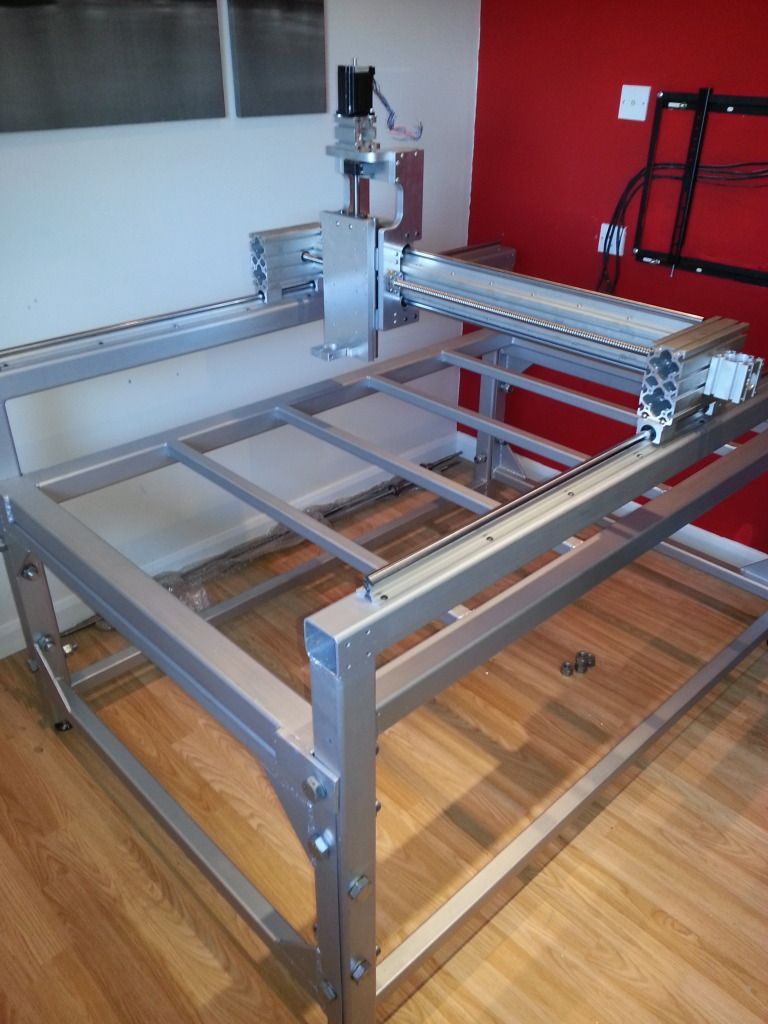
All welding and painting done. Moving onto mounting the y ballscrews now.
-
12-09-2012 #36
Last Activity: 12-03-2021
All the ballscrews are on and nicely alligned now. The PSU is wired up and pumping out 72v @ 16amps. Just need to buy a few odds n ends like energy chain, limit switches, e-stop and shielded cable - if anyone has any for sale, im your man. Im also thinking of buying a 2nm stepper fot the z as oppoesed to the large 3nm ones i have as theyre quite heavy and big? Comments and critisisms welcome!
Last edited by jonbabbz; 12-03-2021 at 06:56 PM.
-
12-09-2012 #37
 Last Activity: 19-01-2024
 Not criticism but slight concerns.? @72V on what I think are 75V drives then your very close to Max with not much room for back EMF. Hopefully you'll be ok but if the drives start tripping then chances are that will be the prob.! . . . I wouldn't be running silly high velocity's just to be on the safe side.
 Originally Posted by jonbabbz

The difference between 2Nm or 3Nm weight wise won't make a jot of difference with these drives/voltages running on ball-screws because the mechanical torque ball-screws produce is awesome and really both are more than enough if all your attaching is a router or WC spindle etc. Also with a Z axis you tend not to run high velocity but more acceleration so the available torque is higher has your not so close to the motors corner speed.
Personally I'd use 3Nm for continuity with rest of machine.
Looking good and soon be cutting.?
Tip: cover them sides before you start cutting else all the crap gets onto ballscrews and shoots every where in all directions. Amazing how much sides really help contain the mess.
Edit:
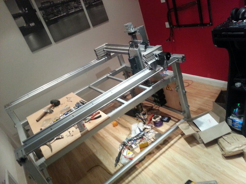
Just spotted that the top box section with rails on is only supported at it's ends. I think you'll find you could suffer from resonance problems at certain depths or feeds esp in harder materials. I Know it certainly will show an effect on finish quality in Aluminium.
Know you've painted it now but I would seriously consider adding some support in the middle, it will pay back in quality of cut believe me.
Edit 2: Eh eh sorry about the add-on's.!! Just spotted that you have the bridge rectifier on a bracket. Really It wants to be on a heat sink, stick it on an old PC CPU heat sink and then fasten that to bracket.Last edited by JAZZCNC; 12-09-2012 at 02:35 PM.
-
12-09-2012 #38
Last Activity: 12-03-2021
The drives are 982's, 80v max so should be ok. Originally Posted by JAZZCNC
Thanks for that, guess ill just use the 3nm ones then. Originally Posted by JAZZCNC
Was hoping within the next couple of weeks, but I damaged (or may have been defective) a linear bearing while assembling it(a couple balls dropped out), so im now waiting for some bearings to arrive. Originally Posted by JAZZCNC
Thanks, never even thought of that!! Originally Posted by JAZZCNC
It will be a real pain in the ass to add these now, so I think ill see what its like before I commit to stripping it completely down. Do you think a strut bolted to the underside of the top box section and bolted to the side of the bed would be adequate for this? i could do that while its still up and still have a few bits of box left over from when I cut up the last bed. Originally Posted by JAZZCNC
Dont worry mate, happy for the info. This one was recommended by Jonathan in another thread. Apparently it doesn't require one, (MB256)? I wasn't so sure - especially with the high amount of current that will be running through it. I suppose its better to be safe than sorry. Ill get one added. Cheeeeeeers Originally Posted by JAZZCNC
-
12-09-2012 #39
 Last Activity: 05-04-2020
 I use the same one and it gets warm, but not hot or anywhere near it's temperature rating so I've not put a heatsink on mine. The peak current running through it is quite high, but here it's the mean current that matters (as that determines the power dissipation) and that is much lower. However if you've got a suitable heatsink lying around then you might as well use it. Originally Posted by jonbabbz
Here I'm running one stepper driver with a 3Nm motor at 4.09A from my lab PSU for testing, note the current:
Last edited by Jonathan; 12-09-2012 at 03:46 PM. Reason: Added image
-
12-09-2012 #40
Last Activity: 19-01-2024
Ye it's a bitch when your balls drop out and before ye know it you have an ASBO. . Originally Posted by jonbabbz

Regards the frame then it's not a big job to do really. Just take 2 diagonal lengths off each leg with brackets at each end that bolt into leg and top rail. . . Simplizz really.
Doing it like this will also allow some adjustment for centre if when testing you find the top rail is slightly bowed.?

 Reply With Quote
Thread Information
Users Browsing this Thread
There are currently 1 users browsing this thread. (0 members and 1 guests)
Similar Threads
-
FOR SALE: Homemade 'Coventry' Type Easy Change Toolholders
By jamesgates1000 in forum Items For SaleReplies: 8Last Post: 04-12-2015, 09:22 PM -
Homemade 3d laser scanner and free software.. looks really good
By Fivetide in forum Laser Machines & BuildingReplies: 2Last Post: 03-09-2012, 01:09 AM -
Homemade CNC Project Help
By chaslam07 in forum Gantry/Router Machines & BuildingReplies: 1Last Post: 04-04-2012, 11:53 AM -
BUILD LOG: Few pics of my homemade CNC mill
By wiatroda in forum DIY Router Build LogsReplies: 22Last Post: 18-02-2011, 09:43 PM -
Homemade desktop CNC - cutting 0.8mm mild steel out the question?
By HankMcSpank in forum General DiscussionReplies: 7Last Post: 16-04-2010, 09:37 AM

Bookmarks