
Thread: Limit Switches
Threaded View


-
12-08-2007 #1

 Last Activity: 10 Hours Ago


 The limit switches are micro switches with an attached lever.Hello can somone please tell me what limit switchs are used for?, going off what i'v seen on a few builds i'm thinking they are put in places that would get them switched when the moving parts of your machine gets to a point where it should stop and go back the way it came ? like a safty device ? is this right or am i well off base with this ?
They are available from RadioShack and the like; the ones shown here are from Mouser.com (part number 101-1203).
They are single pole, double throw and are wired to be Normally Closed, rather than Normally Open.
In this configuration any open connection problems in the circuit will trigger a stop.
If wired Normally Open, an open circuit due to a faulty connection would not be noticed by the software, and no signal would be received when the switch was hit.
All switches are wired in series with each other; therefore, only one pin of the parallel port is used for all switches. All motion ceases when any switch is struck.
The photos are of the 17 x 20 tables.
The switches for the X axis are mounted directly on top of the X end plates; there is one at each end of the table and they are activated when the gantry rail support or gantry end plate strikes the switch.
A probe is attached to the gantry end plate on the spindle side; this is aligned to trigger the switch since the spindle prevents the gantry from touching the X end plate.
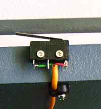
The probe can be anything from a piece of coat hanger to a dowel or paint paddle. Alternatively the switch can be mounted on the X rail support so that it is triggered by a bearing.
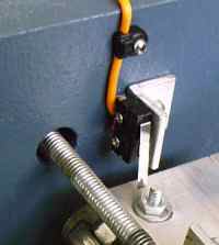
The left picture shows a switch on the Y axis. Again, one is on each end of the axis, and they are mounted onto the gantry end plate with a piece of 3/4" angle.
Their levers are moved by the tails of the machine screws, which hold the bearing truck into position.
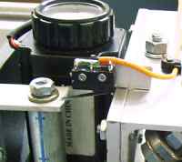
There is only one switch on the Z axis, right image, since the axis can extend farther than the depth of the bed. This kept the options open for different leg lengths on the table. The switch is mounted on the top of the axis, and its lever is activated by the Z rail support.
Below is a schematic for a simple limit switch.
The idea is straightforward.
The parallel port pin is connected to the computer's +5vdc power supply through a 4.7k to 10kΩ resistor; this was a half watt unit. The resistor protects the parallel port from the excess current that it would receive were the pin directly hot wired to the power supply. The 5v pulls the pin high.
Also wired to the same pin on the parallel port are the Normally Closed limit switches linked in series. One wire is connected to the pin and the other wire from the switches is grounded to the computer's power supply low voltage ground. When the switches are all closed, the parallel port pin sees ground. It will be pulled low since the current from the power supply will take the path of least resistance and seek ground through the switches rather than through the parallel port.
When any one of the switches is open the current will travel to the parallel port pin, and the pin will be pulled high. The software is told to stop the machine when the signal is high.
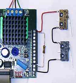
Above is a picture of one end of the Xylotex board with a pair of limit switches and a pull-up resistor. One end of the 10kΩ resistor is connected to the +5vdc terminal on the Xylotex board and the other is connected to the same terminal as one wire from the limit switches; in this image it is terminal 10 (the red wire).
The other wire (black) from the switches is connected to the ground terminal on the Xylotex board.
Note: Sometimes limits will be tripped by the noise in the steppers’ wires. Run the wires separately and/or use shielded cable.
On a servo controlled 4 x 8 foot table, there were still false hits even after the debounce interval was adjusted in the software and shielded wires were used. Finally the problem was solved by placing 4N25 opto-isolators between the limits and the computer.
So...
Limit switches protect the table from damaging itself when the steppers are commanded to move beyond the travel of the machine. With smaller motors, limit switches are not as critical as they are on more powerful tables since the smaller steppers will stall before inflicting extreme damage to the table. However, they may pull the machine out of tune. Larger motors can strip threads or otherwise pull the machine apart. It is easy to jog too far with fast machines such as the belt drive and rack and pinion tables, and limits keep small mistakes from becoming major problems.
Hope this clears up any questions you may have about limit switches !Last edited by Lee Roberts; 18-12-2008 at 08:35 PM.
.Me
-
The Following 2 Users Say Thank You to Lee Roberts For This Useful Post:

 Reply With Quote
Thread Information
Users Browsing this Thread
There are currently 1 users browsing this thread. (0 members and 1 guests)
Similar Threads
-
EMC2 home/limit switches... only acting as limit?
By vputz in forum LinuxCNC (EMC)Replies: 4Last Post: 15-10-2014, 09:51 AM -
Limit Switches
By Leadhead in forum General ElectronicsReplies: 1Last Post: 16-10-2013, 10:41 AM -
Limit switches and Mach3
By cropwell in forum Artsoft Mach (3 & 4)Replies: 1Last Post: 06-03-2013, 10:51 AM -
Limit Switches with LED's
By manofgresley in forum General ElectronicsReplies: 30Last Post: 02-01-2013, 03:08 PM -
Uniport and limit switches.
By D-man in forum General ElectronicsReplies: 14Last Post: 13-02-2012, 11:37 PM

Bookmarks