
Thread: Wiring home and limit switches
Hybrid View


-
18-12-2008 #1

 Last Activity: 1 Hour Ago


Wiring limits and home switches can be handled in a multitude of ways.
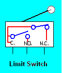
But first you need to know what software you plan to use before deciding on a method. Typically limit switches have both normally open contacts (NO) and normally closed (NC) contacts. Depending on how you want to wire you can wire them in series or parallel with other switches.
For example, CNCpro utilizes one input pin for each axis. Commonly that one input pin is wired to two fixed switches, one for home and the other for limit. It could also be used with one switch that moves with the axis and either via ramps or mechanical triggers actuates at the travel ends. Home is defined by the software setup as to which direction the axis is traveling when the switch activates. When using stepper motors, there typically isn't a need for more than two switches per axis. Servo's on the other hand, may need two dedicated limit switches to protect from a open loop failure causing a run away servo.
MACH3 software is very versatile and can be configured in many different ways. A common way is to have a seperate home switch for each axis, and one pin to all of the limit switches wired in series utilizing the normally closed contacts.
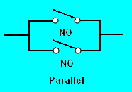
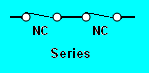
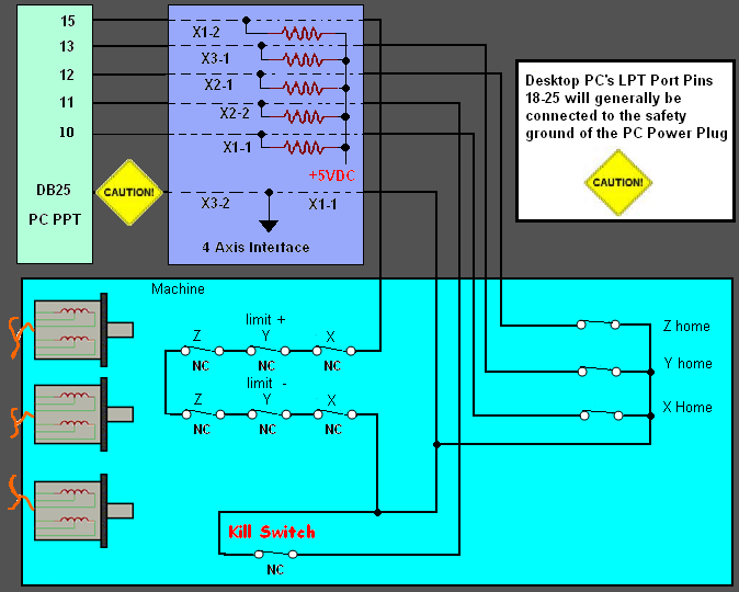
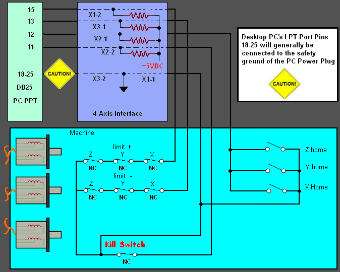
Below is two methods of wiring limit, home and kill switches. By utilizing a series wiring of normally closed limit switches, when one switch opens it sends a signal to the computer to stop issuing step pulses to the axis drive motors. In parallel, you have to use normally open switches to sense a switch activation. The top drawing utilizes independent normally closed switches for a home for each of 3 axis and is more compatible with MACH3. The bottom is another method to do home switches.
Utilizing normally closed switches is more noise immune, and thus reduces the risk of false switch actuation. The other noise benefit from utilizing NC contacts is coupling noise back into circuits and wiring for step/direction motor controllers.
Last edited by Lee Roberts; 18-12-2008 at 08:33 PM.
.Me
-
The Following User Says Thank You to Lee Roberts For This Useful Post:
-
21-01-2009 #2
 Last Activity: 4 Weeks Ago
Lee,
I am using as stated in other posts here a Stepperworld which has the ability to add switches to it on the board. I am having problems uploaing the image and will try later. The switched are labeled S4 through S6 plus ground and was wondering what would be the best way of setting up a circuit board to complement Mach3 with that set up to be able to set either boarder switches or zero points.
Thanks ahead and will try again to load the file. Does the system prefer .GIF or JPEG for uploads? As I reduced it with GIMP to 800x600 and saved it as such but it is still seeing it at the larger file size even though the file is coming from a different saved point in the drives.
Michael
-
21-01-2009 #3
Last Activity: 1 Hour Ago
Whats the file size ?
.Me
-
22-01-2009 #4
Last Activity: 4 Weeks Ago
16.8KB is that to big?? most file groups take half a Meg last I knew??:confused:
 Originally Posted by Lee Roberts

Michael
-
22-01-2009 #5
Last Activity: 1 Hour Ago
Yea the file size is set to 500k, see here: Click Me...
.Me
-
26-09-2010 #6

 Last Activity: 27-09-2010
Hello Lee - I have just seen your wiring diagram and thought you might have a view on the following
I have just started getting the equipment together to add limit/home switches to my machine, and have found the following diagrams
The first has three wires running to all switches while the second has a serial connection to the switches which includes the emergency cutout. I can see how the second works , but am unable to see why the first has the three wires. - The connection board is the same as shown :
Are you able to comment on this set up and how it compares with your diagram
Would apprcieate anything you have to say
Thanks
Ken
-
26-09-2010 #7
 Last Activity: 17-03-2017
The reason is that the inputs to the board have to be switched between 0v and +5v. generally the inputs are pulled up to +5v by a resistor on the board and the switches then short the input to ground. An alternative approach is to use both poles of the switch to switch the input line between a 0v wire and a +5v wire. This is how the home switches in the first diagram are wired, as individual inputs. But the same approach is used for the limit switches in the lower part of the diagram and this is just wrong... in fact the way that is wired when one limit switch is activated it puts a short from 0v to +5v, which will probably have the effect of stopping everything but for the wrong reasons.... I would ignore that and go for the single chain of switches. However I would seperate the PANIC switch from the limit switches. A panic switch should always control a relay which supplies power to the motors. That relay MAY have a contact that does the panic input to the breakout board and thence to MACH3 as per these diagrams... one should NEVER rely on MACH3 to stop the motors in an emergency, the panic switch should always act directly...
-
The Following User Says Thank You to irving2008 For This Useful Post:
-
28-09-2010 #8
Last Activity: 3 Days Ago
It is interesting what hitting the Emergency stop will do, if too heavy a cut is going to damage the spindle then killing power would probably be ok, but if someone has a hand trapped then that is not the best option. Originally Posted by irving2008
I worked on japanese grinding machines where all end of travel prox switches and the emergency stops were wired into the omron c500 machine controller. If the emergency stop button was pressed, the spindle would turn off, the table would retract in case someone was trapped, then power would go off turning off hydraulics and all power.
-
05-07-2013 #9
Last Activity: 11-07-2017

Hi guys, I'm working on the control panel for my cnc 4 axis router (2nd x axis to be slaved). I will be running a 24v safety system and within this will be 2x e-stops, limits and home switches.
When triggered the 24v system will cut power to the 70v supply to the steppers but I'm confused how the triggering item I.e. e-stop will communicate to the bob to show Mach 3 what has caused the stop if wired in series as surely any item within the parallel wiring loop could be seen as the cause? Or is this the case, Mach just sees a fault and its down to the operator to find the cause?
Are relays typically used from the 24v system to send the control signal to the 5v break out board inputs?
I am working on a diagram for my system which could do with being looked over by someone that knows what they are talking about, should have this posted mid next week if you could comment. I have seen loads of diagrams of set ups but want to draw one for my system to get it clear in my head as this side of it is not my strong point. Cheers.Dan
-
06-07-2013 #10
 Last Activity: 19-01-2024
Hi Dan,
The way it's done is to series wire the E-stop and limits thru the 24V coil (coil not contact) of a relay. Then take the +5V signal from the BOB and run thru the contact of same relay and back to -5V on BOB.
This then informs Mach an Estop has happened so stop the G-code from running.
Inside mach you just set inputs up to watch same pin for both e-stop and limits. This does mean fault LED's in Mach will show both E-stop and limits tripped at same time. If you want to know which individual switch tripped then only way round this is to use an input for each switch. Has you can see this will need many inputs which you don't have and In practice this doesn't matter much has you'll know what's caused it.
The other contacts of the relay can then be used to either control other relays or directly turn something off IE: 70V supply.
Home switches shouldn't be run thru relays has the delay is too long and makes them inaccurate. Just use the 5V signal from bob for relays has your only using it when homing so very rarely do they get affected by noise etc so ok to do so.
They can also be wired in series and just use 1 input has Mach only homes one Axis at a time and actually doesn't care where the switch is pressed because it just records the coordinates for the Axis it's referencing at the time when it see's the input trigger then does the same again for next Axis when sees input trigger again.
In theory and practice when wired in series you can set the home position for X axis by pressing Z or Y axis switch because it just records the position it's at for Axis it's referencing when input fires.
Note If your using 2 motors slaved to an axis then you must have each motor on separate inputs. One can be wired in series with other axis but the other must be on it's own separate input. If not then Mach can't individually home each motor for squaring gantry.
-
The Following 5 Users Say Thank You to JAZZCNC For This Useful Post:

 Reply With Quote
Thread Information
Users Browsing this Thread
There are currently 1 users browsing this thread. (0 members and 1 guests)
Similar Threads
-
EMC2 home/limit switches... only acting as limit?
By vputz in forum LinuxCNC (EMC)Replies: 4Last Post: 15-10-2014, 09:51 AM -
24v Limit/Home switches. How to..?
By Wal in forum General ElectronicsReplies: 6Last Post: 17-11-2013, 05:52 PM -
Limit Switches with LED's
By manofgresley in forum General ElectronicsReplies: 30Last Post: 02-01-2013, 03:08 PM -
Limit/home switches - how are you mounting 'em?
By HankMcSpank in forum General DiscussionReplies: 2Last Post: 13-11-2011, 01:42 PM -
The best solution for limit / home switches on a mill is .....what ?
By NICKMODELMAKER in forum Gantry/Router Machines & BuildingReplies: 1Last Post: 29-05-2010, 01:38 PM

Bookmarks