
Thread: Machine Problem - Rockcliff
Hybrid View


-
15-02-2009 #1

 Last Activity: 8 Hours Ago


Right guys,
I'v got an issue with my machine, i cant work out what it is thats giving me this issue but im hoping you will know or know somthing i'v missed off my check list.
Ok i'v checked:
1. Measurements in my drawing
2. Toolpath settings in my drawing
3. Tool settings in my drawing
Ok so thats what i have checked pre Mach3.
In Mach3 i have checked:
1. Motor tuning (1280, 200, 50), drivers setup for 1/8th step
2. Zero All Axis's, REF All Home updated to new zeros
thats what i have checked pre machine (Rockcliff)
On the machine i have checked:
1. Rails + Bearings (levels, square's)
2. Drivescrews + Nuts (delrin drive nuts all nice and tite, leadscrews dont seem to have any issues.)
3. Checked Calibration (machine moves 20mm psyically when moved/jogged 20mm on the screen for mach3 (DRO?) )
My problem is:
The part is 3mm under size all round, the center hole should be 43mm but its coming out at 44mm (note this is only 1mm error), the bottom of the part (bit that fix's to the machine) should be 80mm across, its coming out at 77mm.
Any ideas guys? I thought maybe i'v not set the right end mill size in the design but thats set to a 3mm End mill and that is what i have in my spindle.
I'm telling the toolpath to cut on the "outside" of the vector, i really cant think of anything else i can check.
Please any info i can provide you with please ask and ill reply more or less instantly with an answer. The GCODE is posted below if you would like to look at that.
Cheers, Lee :confused: :( :( :confused:
Last edited by Lee Roberts; 15-02-2009 at 09:14 PM.
.Me
-
15-02-2009 #2

 Last Activity: 30-01-2010
looking at the gcode, it doesn't look like you run a finish pass.
You'll get tooling flex so you should have the software leave about .5mm or less
for the finish pass, it can take the last pass at full depth and it will clean up any
ridges left from the multipasses during roughing.
-
15-02-2009 #3
 Last Activity: 23-09-2017
Checked the code and the inner circle is 40mm and the outer block is 83 so they are right given a 3mm tool.
Got to be scaling, setup or machine flex.
.
-
15-02-2009 #4
Last Activity: 03-10-2018
Hi Lee,
Something else to check - is the circle round or oval? It looks very much like you have set the X axis up with the wrong data. If the circle is round then the Y axis is also out. You have not said whether the piece is the right height in the Y axis. Apologies - just looked at your post again and you say it is 3mm out all round. As mentioned by Kwackers, some accurate measurement is needed to determine if the error is cumulative. i.e. gets larger the further the axis travels. If this is indeed the case, you will need to double check your leadscrew pitch, stepper steps and steps per mm.
Mike
-
16-02-2009 #5
Last Activity: 01-12-2009
Hi Lee
If the centre hole is larger than it should be, but the outside is smaller then it can't be a scaling problem. Is the machine loosing position under cutting load conditions. Try taking a very fine cut or try modling board or something soft to machine to see if that is OK. Also check calibration over at least 200mm movment.
Thanks
Roy
-
16-02-2009 #6
 Last Activity: 14-02-2010
It almost sounds like its programed to cut center line instead of edge..... but if that were true then your inside would be just as off as the outside and you've already checked that.
I'm wondering if your not losing position under load like captainresonator has mentioned. You would think though if that were the situation though you'd not have a uniform error.
-
16-02-2009 #7
 Last Activity: 20-05-2011
What size of guide rails did you use?
What type of lead screws did you use (metric/inch)
What units are you using? (you answered that already = mm)
What CAM tool are you using? ie post processing of CAD into GCODE
What are you using for the spindle motor? (how heavy is it?)
Can you post photo of the machine? Showing the x-z axis mount in particular.
My hunch is that there is a lot of movement in the tool in the Y plane. This is due to over large tolerances in the bearing blocks (I have the same problem after 18 months) and the X-axis rail mounts. The MDF bearing blocks compress with vibration and lubricating oil thus allowing for a very large movement in the tool typ. 5mm
So to prove the hunch ... park the spindle in the middle of the X plane. Put the tool into the spindle motor. Drive the tool down to just above the table. Turn EVERY thing OFF. (or risk loosing fingers). Pull on the tool and see what movement there is and what force is needed to move it. Look for flexing in the guide rails, movement in the bearing blocks, look for sleeves falling out of their mounts (oh yes!).
Templecorran
--------------
where the light was kept in the Dark Ages
-
18-02-2009 #8
Last Activity: 8 Hours Ago
Firstly Thanks and apologies to you all…
Here’s why…
I said I had Checked Calibration and the machine moves 20mm physically when moved/jogged 20mm on the screen for mach3. Ok well that was true however only to my steel ruler and in a rushing over enthusiastic way.
I also said I had checked my Tool settings in my drawing, well that is true also but I hadn’t set the Stepdown/pass’s correctly and the two 5mm pass’s used to cut the part in my first post was basically me pushing a weak machine to fast and to hard perhaps?
So I read over what you have all been posting and sending me via email, along the way I picked up a few things I really needed to look at properly, mainly calibration and backlash.
In all the excitement to getting my machine “up and running” these are both things I didn’t really give much attention to and for that I’m sorry for taking up everyone’s time but in away everyone helped because it made me step back and take a proper look at everything.
It didn’t help that my digital calliper went flat on me last week (the battery!), what I have now basically done is run calibration tests on each axis, it turns out the machine was out in all 3 axis’s .
.
So I got everything down on paper, when I run the Axis Calibration it kept setting up my Y axis to some really odd settings I don’t know why because the X and Z it didn’t seem to have a problem with as they both got the same settings assigned to them from mach, then I read up about how to adjust for backlash and then proceed to setup mach to account for the backlash on all 3 axis's.
My calliper is only a cheap one so working in mm I have only got 0.0 on the actual readout display of the calliper, anyway I did the above and I now seem to be spot on in all 3 axis’s, I went 100mm on all 3 axis’s however I only did this in 1 direction on each, dose that matter? I know you said to go to atleast 200-250mm but my calliper will only goto 155mm .
.
Once I was happy that I wasn’t going to get it much better, I drew out (using a marker) a number of different size boxes, I then checked they were to the right sizes and square.
Once I did that I then tried cutting the part in my first post again, only this time I only stepped down on each pass 1mm at a time and I just made 2-3 passes.
When I checked the sizes of the part I was still out 1mm here, ½ a millimetre there and it wasn’t quite right. I then went back to the forums and read some of your new posts, the one by AlexBanich who said:
I'm wondering if you’re not losing position under load like captain resonator has mentioned. You would think though if that were the situation though you'd not have a uniform error.
Well I then pulled out one of the very first drawings I did on a bit of chipboard, I looked at the sizes and to my surprise they were quite close (if only I had calliper, when I drew it out!).
I then started to question if I was losing position under cutting load. So I put it to the test but this time I only did ½ a millimetre pass’s.
While there was room for improvement it was the best it had been so far!
So, I then did it again, this time I tweaked my spindle speed so that I wasn’t getting any smoke from the cutter but the speed was enough that everything was still running/cutting smoothly. In the picture below you can see what the result was:
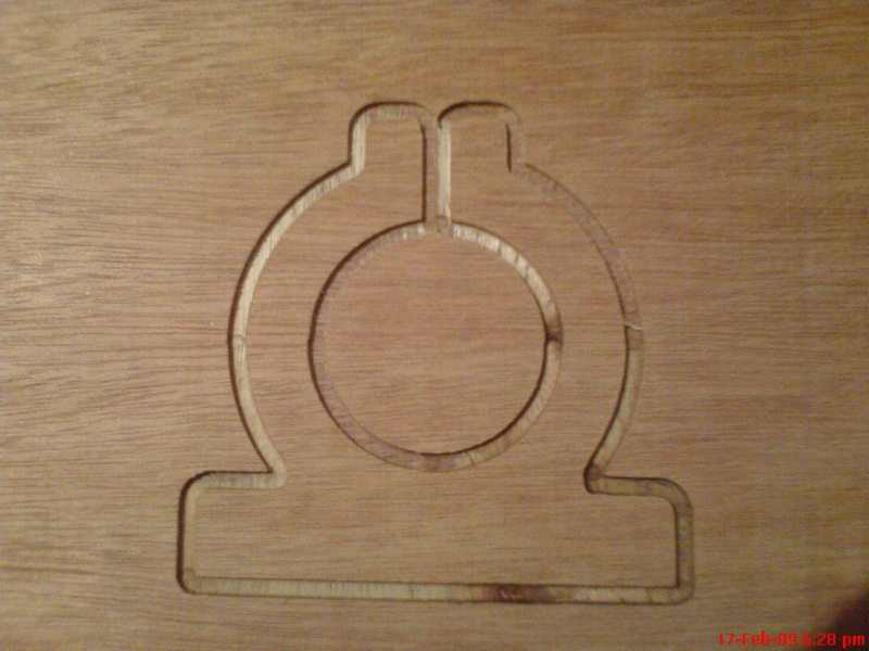
all checks done on sizes and we have a WINNER!, fair enough my calliper is only cheap so I can’t really say its spot on.
So to sum up:
I wasn’t accurate enough in my so called original “calibration”.
I learnt that the Steps per settings need to be calculated properly.
That Backlash compensation is your friend when you want to start really fine tuning the calibration, so use it Lee!
The other thing that I have also discovered is that quite frankly my Rockcliff is really sensitive when under load, if I try to make passes above ½ a millimetre; the results are no good/wrong.
I used 12 1/2mm round rail and mdf for the build and because of this the machine is weak? Fragile? I don’t know what the best description is.
So ill do some more cutting and work out what is best or what my sweet spot is so to speak but it’s not going to be great in terms of how fast I can machine parts but I’ve walked away with some more knowledge and better understanding of what I’m dealing with so I guess that’s great.
I think there is a few other things I can do to help give the machine a fighting chance, the cutter I have been using is a 3mm, 3 Flute End Mill it cost about £1 from Hong Kong and it now looks like it’s been thro the war.
I’ve got myself some dormer ends mills and I’m thinking about coming down in cutter diameter to see if that helps at all. So time will tell!
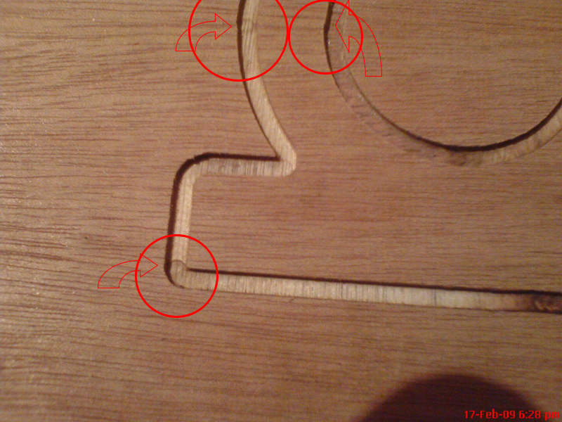
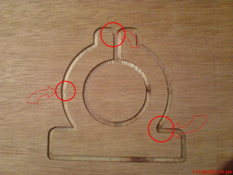
The problem I seem to have now is, when the machine is running it seems to cut about 35mm then pause's for a second, then starts off again.
It dose another 35mm, then another pause, and it does this until the job done. Is this right?
It only seems to have started doing it since I setup backlash adjustment on mach. I wouldn’t mind but when it starts to take off again its actually that sensitive the cutter is moving off line as it starts to cut into the material again, this is now also giving a discrepancy In the cut part, hopefully you can see what I mean in the pick below:
I will update again later tonight with a video of the machine cutting so you can see what is going on.
Again, Thanks for all your input guys your suggestions all helped me along the way to finding the “answers” and for that I’m very much grateful.
Ok its now gone 2:30am and its time for bed, catch up with you all later.
Cheers,.Me
-
18-02-2009 #9
Last Activity: 03-10-2018
Lee,
The discrepancy and the pauses will be the backlash compensation. On a change of direction of an axis, Mach pauses the cut while the backlash is taken out. I am sure there is somewhere within Mach that lets you change the speed of the update but I'm not sure where it is as I do not need backlash comp on my machine - apologies, I don't mean to gloat :)
Mike
-
18-02-2009 #10
Last Activity: 20-05-2011
What are you using for the spindle motor? If you intend to use anything heavier than a Dremel, then you really need to consider using larger diameter rails. The flexing in a 1/2" (12.7mm) rail is too great for anything other than cutting polystyrene; seriously. Nick at RockCliff stresses that in his forums that his initial designs used 1/2" and he has since up graded to 5/8" or 16mm. It is amazing how much more rigidity that extra 3mm provides.I used 12 1/2mm round rail and mdf for the build and because of this the machine is weak? Fragile? I dont know what the best description is.
As for MDF -- if you used the 19mm as spec'ed, you will have ample strength for cutting even light gauge metal sheet.
I have been using a B&Q 1020W £20 router with a modified base -- it is heavy at 2kg, and with the Z motor at 1.85 Nm I can't drive it quicker than 300 mm/min or it stalls out. I'm using motor driver modules from http://www.jafmotion.co.uk/motordrives.htm that I think need to be used with caution.
The other thing to ask is do you need backlash compensation?
To prove it maybe cut a square with your 3mm cutter and repeat it many times. If the track is still only 3mm after 10 or 15 repeats, then you do not need backlash compensation.
I need to get a new X/Z interface plate made in Al with bearing blocks in Al that won't shake loose in time.
My machine was built using 19mm MDF as per the plans; 16mm and 5/8" guide rails (redeemed from plotters and ebay), and Oil-Lite sleeve bearings; Lead screw 10 x 1.5 mm standard threaded bar from B&Q. FL57STH76-2808B motors from http://www.motioncontrolproducts.com/nema23.html.
cheersTemplecorran
Where the Light was kept during the Dark Ages

 Reply With Quote
Thread Information
Users Browsing this Thread
There are currently 1 users browsing this thread. (0 members and 1 guests)
Similar Threads
-
Boxford 125 TCL Searching for machine problem
By dragon in forum Boxford LathesReplies: 1Last Post: 28-12-2014, 09:27 PM -
Location of machine problem
By Eugene in forum Computer SoftwareReplies: 2Last Post: 27-01-2011, 07:00 AM -
Machine problem. Heiz. Blew up on me !
By xchipx in forum Heiz CNC RoutersReplies: 2Last Post: 03-04-2009, 01:08 PM -
Machine problem with softlimits mach3 & Estop
By Steve-m in forum Artsoft Mach (3 & 4)Replies: 9Last Post: 12-01-2009, 05:38 PM -
NEW MEMBER: Rockcliff
By Rockcliff in forum New Member IntroductionsReplies: 3Last Post: 05-08-2007, 02:32 AM

Bookmarks