
Thread: Limits, homes, override switch
-
26-02-2016 #21

 Last Activity: 29-12-2022


I think all the inputs are 5V. How would I wire the resistor (I mean, I know it's a simple wiring diagram), but how do you actually wire it. Is there any kind of "terminal resistor" ?
-
26-02-2016 #22

 Last Activity: 10-12-2021
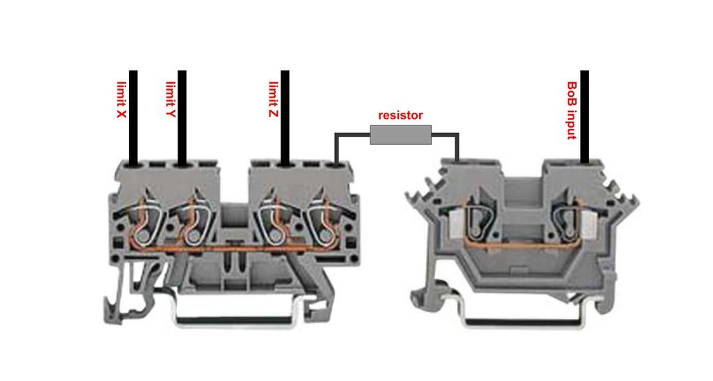
 I saw only once a special resistor socket to be inserted in terminal block. And there are terminal blocks with resistors, diodes, electronics fitted inside.
 Originally Posted by eurikain

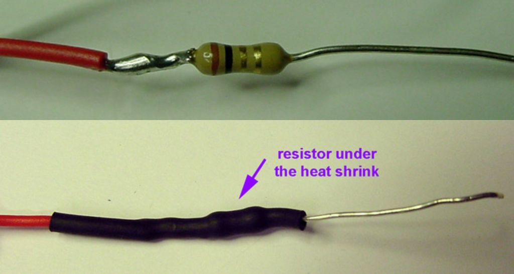
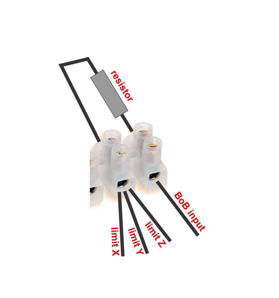
The simple way is to solder the resistor to the wire end. The third method is not recommended unless you solder the input wires together.
-
19-10-2016 #23
 Last Activity: 15-01-2024

 How about using solid state relay? It doesnt have moving parts so no delay or it is very very tiny? Originally Posted by JAZZCNC
Isiųsta naudojantis SM-G900F Tapatalk 4 Lt
-
19-10-2016 #24
 Last Activity: 19-01-2024
 Better but still not recommended or required. STR's also tend to fail in the on state which isn't good either. Originally Posted by valdis034
-
19-10-2016 #25
Last Activity: 15-01-2024
So the best option is to use resistor and take 24v straight to bob?
Isiųsta naudojantis SM-G900F Tapatalk 4 Lt
-
19-10-2016 #26
 Last Activity: 28-05-2023
The LJ12A3-4-Z/BX sensors I use with this board are NPN - the output of the sensor goes to GND when triggered - which is what you want. The board has pull-up resistors so that the untriggered state is strapped to 5v. You don't need resistors as the 24v power to the sensor is limited in current to 2.4mA and in voltage by an internal zener diode in the switching circuit. Originally Posted by paulus.v
Last Activity: 28-05-2023
The LJ12A3-4-Z/BX sensors I use with this board are NPN - the output of the sensor goes to GND when triggered - which is what you want. The board has pull-up resistors so that the untriggered state is strapped to 5v. You don't need resistors as the 24v power to the sensor is limited in current to 2.4mA and in voltage by an internal zener diode in the switching circuit. Originally Posted by paulus.v
These sensors have been designed to make connection simple and to have wide application, why do people then have to make things complicated. If you complicate you introduce the possibility of design faults and unreliability.
I lose the will to live every time someone mentions a relay in a homes circuit.
For Pete's sake, there is plenty of info and advice on t'Interweb. Do a bit of searching online before you regurgitate the same old questions.
Happy bloody christmas !!!!
Rob

 Reply With Quote
Thread Information
Users Browsing this Thread
There are currently 1 users browsing this thread. (0 members and 1 guests)
Similar Threads
-
feedrate override using rotary momentary switch?
By routercnc in forum General ElectronicsReplies: 8Last Post: 26-02-2015, 10:11 PM -
Proximity switch NPN or PNP
By Matt81 in forum General ElectronicsReplies: 9Last Post: 19-04-2014, 11:38 AM -
stepper acceleration rate - limits?
By dsc in forum Stepper & Servo MotorsReplies: 11Last Post: 02-03-2014, 02:25 PM -
limits on mill table
By John11668 in forum Gantry/Router Machines & BuildingReplies: 5Last Post: 31-08-2011, 06:46 PM -
Limits or homing switchs???
By Ross77 in forum Computer SoftwareReplies: 11Last Post: 28-03-2010, 03:17 AM

Bookmarks