
Thread: Thor, or should that be Zeus?
Hybrid View


-
01-03-2016 #1

 Last Activity: 4 Weeks Ago


Great! Now even i am surprised. I will be following with great interest. OMG

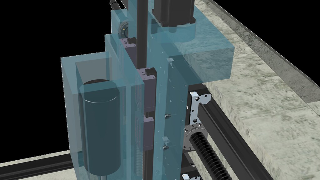
Charl, now i see what your are up to. Would you like to see the drawing of my Z on mine big machine? It would be very appropriate if you decide on using 3kw-5kw high speed spindle. The overhang i achieved is ridiculously low. Unfortunately still not in proper cad but Sketchup. But you could draw some ideas from it.
Or you will go the BT30 way?Last edited by Boyan Silyavski; 01-03-2016 at 03:44 AM.
-
01-03-2016 #2

 Current Activity: Viewing Is a 600W AC servo better than a matching asyncrounous single phase AC motor?
Hi, yes, please. Any inspiration, ideas, comments, feedback appreciated. Feel free to email to me, Ill convert it.
Current Activity: Viewing Is a 600W AC servo better than a matching asyncrounous single phase AC motor?
Hi, yes, please. Any inspiration, ideas, comments, feedback appreciated. Feel free to email to me, Ill convert it. Originally Posted by Boyan Silyavski

At the moment, I am looking at options for spindles. Current view is to either have 4KW Chinese spindle or perhaps something more expensive (if budget allows) something better.
Id love to go to BT30 but not designing around this at present.
-
01-03-2016 #3
 Last Activity: 1 Day Ago


Theoretically the bearing blocks should be bolted to the gantry and the rails to the bottom of the bed. If you put the blocks on the bed you introduce unnecessary overhangs and add a lot of metal supporting rails that does nothing. It should be more A frame and less triangular. OTOH, what do I know? -freaking smileys don't work-
-
01-03-2016 #4
Current Activity: Viewing Is a 600W AC servo better than a matching asyncrounous single phase AC motor?
Thanks. Point taken. This was pointed out too (off this thread) in the design. Ill make the changes. Originally Posted by Robin Hewitt
-
01-03-2016 #5
 Last Activity: 4 Days Ago
Wow Chaz - excellent thread. Great to see someone putting a bit of thought in and going for it!
I would lean towards Thor, the top design, although both would do well.
In my new mk4 design I had to go with moving gantry because I still need to cut large wooden sheets, but with your brief these designs are excellent.
If the granite epoxy is too difficult to make/cast then it looks like it could be done with say 150x50mm sections all welded together. Then backfilled with epoxy granite. Weld on some flat 10mm bar where each rail will go, get it skimmed flat, and there you are.
For the spindle I wonder if you could have a bolt-on high speed spindle for aluminium (router mode), then bolt on a heavily geared down spindle for steel (mill mode). Or have both in place so you can choose.
Good luck with however you choose to develop this - watching with interest.
-
01-03-2016 #6
Current Activity: Viewing Is a 600W AC servo better than a matching asyncrounous single phase AC motor?
Thanks. We have discussed a dual spindle setup. I might want to stick a grinding spindle in there too somehow :-) Originally Posted by routercnc
I'm looking at rail options for the Z at present, I have some other options to consider although already spent a small fortune on the parts thus far. I will have leftovers, will likely be put into a DIY CNC Lathe.
-
01-03-2016 #7
Current Activity: Viewing Is a 600W AC servo better than a matching asyncrounous single phase AC motor?
Just to confirm you are referring to swapping the rail and cart here on the Z Axis? Originally Posted by Robin Hewitt
-
02-03-2016 #8
Last Activity: 1 Day Ago
I was actually referring to the X. At the bottom you have two linear rails bolted to an enormous structure, most of which is superfluous, you only really need the bit under the gantry. Originally Posted by Chaz
If you fit the linear blocks to the bit under the gantry and the rails to the table then the support will always be under the tool.
You lose an unnecessary overhang.
-
02-03-2016 #9
Current Activity: Viewing Is a 600W AC servo better than a matching asyncrounous single phase AC motor?
Ah, ok, understood. Originally Posted by Robin Hewitt
I'm just trying to find the reference design / document that I used. I did note that this is not final but the shape (with more support) is basically a triangle.
I am however more than happy to make changes based on experience, one of the reasons why I have started this thread.
-
02-03-2016 #10
Last Activity: 4 Weeks Ago
The way i see it, if you go with high speed spindle, fixed gantry would be better, if you go with servo motor and Bt30, the VMC shape will be better. So at the end there is not so much to consider which shape you go.
With that size bearings and rails length, overhang will be irrelevant. You could try to make it small, just for a designers satisfaction though, but its not necessary.

 Reply With Quote
Thread Information
Users Browsing this Thread
There are currently 4 users browsing this thread. (0 members and 4 guests)

Bookmarks