
Thread: ebay power supply
Threaded View


-
31-07-2010 #11

 Last Activity: 08-02-2014


A couple of hi-res images if needed ...
http://www.i2net.me.uk/files/cnc/min...oard-hires.JPG
http://www.i2net.me.uk/files/cnc/min...oard-hires.JPG
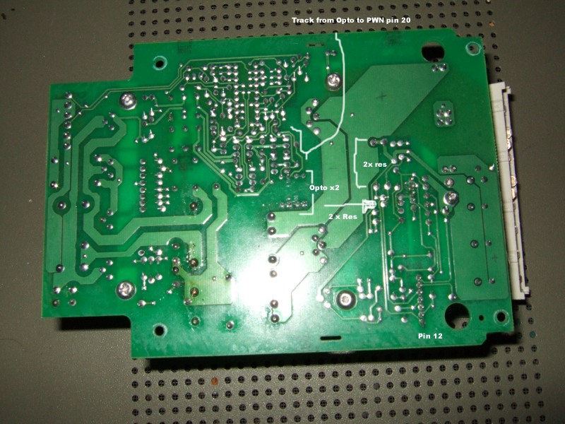
Back of the board showing the 2 optos (2 x 4 pins), the track feeding pin 20 (Error Amp) on the PWM and the 4 res making up the 2 voltage dividers. (ignore the pencil marks, they may or may not be correct!)
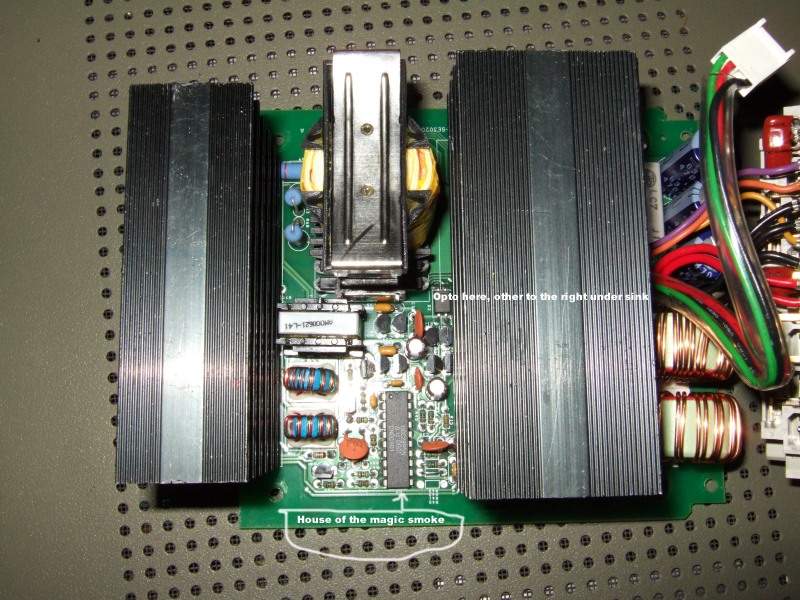
Top of board, only 1 of the optos is visible.
Close-up of output coils, one of the two large voltage divider resistors marked (R34). The large resistor from the second divider (R11) is right next to it.
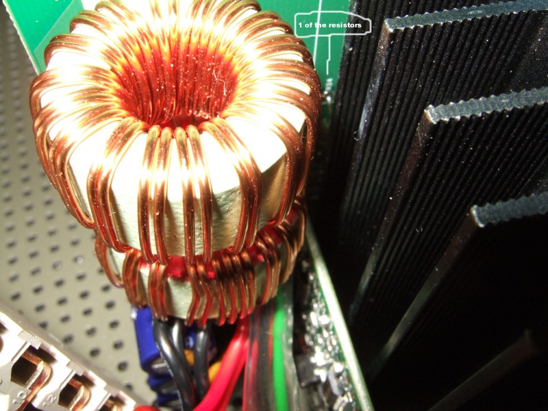
The zener is just so I can set up your test circuit... still not found one :(
My idea is to modify one or both of the voltage dividers by fitting parallel resistors, this is a nice easy modification and so long as we don't ask for the impossible the whole of the control circuit should play along with us :)
Example:
In fixed mode the op voltage is 42.9v and the voltage at the centre of each divider pair is 4.29 volts. This 4.29 is the critical voltage in fixed mode, the control circuit will do every thing it can to maintain 4.29 volts at the centre of the divider pair. If we reduce the value of the lower resistor in the divider then this resistor will drop fewer volts and the divider ratio will effectively increase. If we select a value that gives us an 11:1 divider for example, in order to maintain 4.29v the output voltage would have to be 47.19 volts. Yay, in theory :)
Reducing the value of the upper resistor in the pair reduces the divider ratio which should allow us to modify the output voltage range in variable mode.
What I don't know for certain is the value of the resistors in the pair, my colour vision is not so good so I can't read the value of R34 or R11.Once we know the value of one of the resistors we can calculate the rest :)

 Reply With Quote
Thread Information
Users Browsing this Thread
There are currently 4 users browsing this thread. (0 members and 4 guests)
Similar Threads
-
can I have my power supply in a seperate box?
By nobby in forum General ElectronicsReplies: 1Last Post: 12-06-2013, 11:33 PM -
Minimal-cost Power Supply Strategy - Repurpose Laptop Power Supplies
By LoveLearn in forum General ElectronicsReplies: 0Last Post: 25-01-2012, 09:29 PM -
FOR SALE: 50V 20A Power supply
By Jimmybristol in forum Items For SaleReplies: 8Last Post: 30-05-2011, 11:01 PM -
12V Fan off 230v power supply ?
By Buba b in forum General ElectronicsReplies: 5Last Post: 02-03-2010, 09:51 PM -
power supply
By hitmythumb in forum General ElectronicsReplies: 6Last Post: 21-06-2009, 10:27 AM

Bookmarks