
Thread: ebay power supply
-
30-07-2010 #51

 Last Activity: 17-03-2017


Where did you think the optos are?
Ideally would want to be able to force the voltage down further, tho that might not be viable...
Where were you going to put the zener?
Since I've fried this board anyway I think I'll pull it to bits, get easier access to the parts....Last edited by irving2008; 30-07-2010 at 10:39 PM.
-
31-07-2010 #52

 Last Activity: 08-02-2014
A couple of hi-res images if needed ...
http://www.i2net.me.uk/files/cnc/min...oard-hires.JPG
http://www.i2net.me.uk/files/cnc/min...oard-hires.JPG
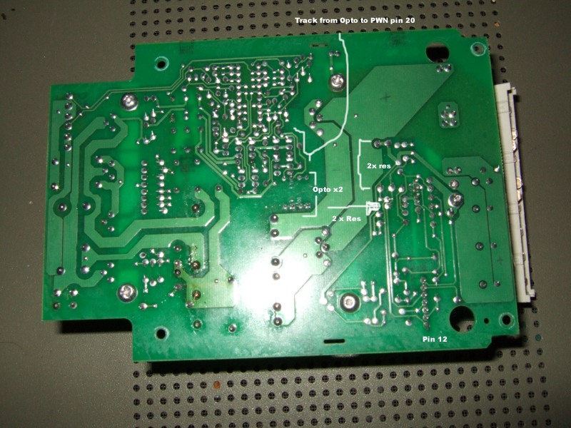
Back of the board showing the 2 optos (2 x 4 pins), the track feeding pin 20 (Error Amp) on the PWM and the 4 res making up the 2 voltage dividers. (ignore the pencil marks, they may or may not be correct!)
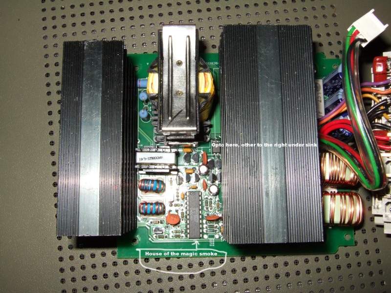
Top of board, only 1 of the optos is visible.
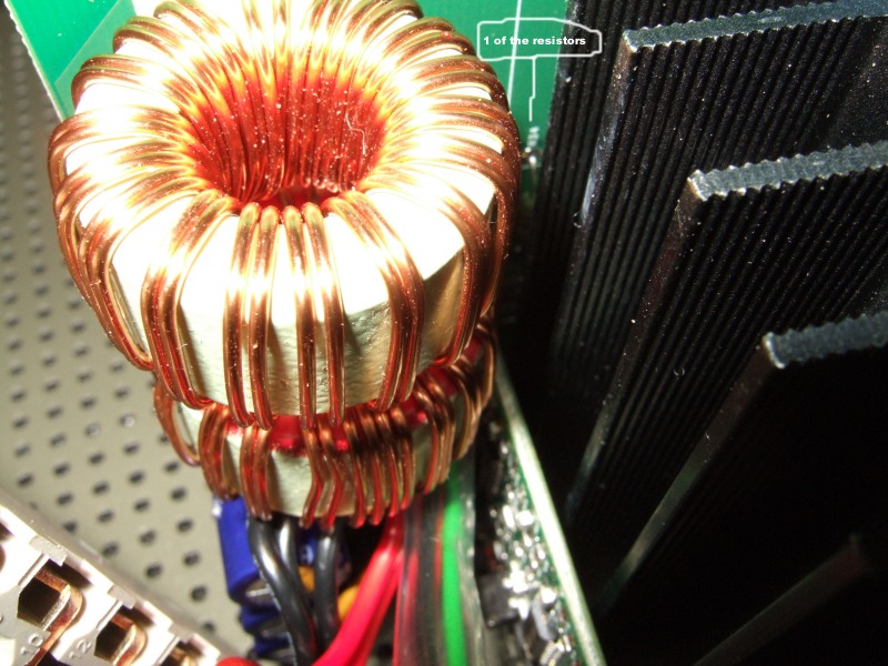
Close-up of output coils, one of the two large voltage divider resistors marked (R34). The large resistor from the second divider (R11) is right next to it.
The zener is just so I can set up your test circuit... still not found one :(
My idea is to modify one or both of the voltage dividers by fitting parallel resistors, this is a nice easy modification and so long as we don't ask for the impossible the whole of the control circuit should play along with us :)
Example:
In fixed mode the op voltage is 42.9v and the voltage at the centre of each divider pair is 4.29 volts. This 4.29 is the critical voltage in fixed mode, the control circuit will do every thing it can to maintain 4.29 volts at the centre of the divider pair. If we reduce the value of the lower resistor in the divider then this resistor will drop fewer volts and the divider ratio will effectively increase. If we select a value that gives us an 11:1 divider for example, in order to maintain 4.29v the output voltage would have to be 47.19 volts. Yay, in theory :)
Reducing the value of the upper resistor in the pair reduces the divider ratio which should allow us to modify the output voltage range in variable mode.
What I don't know for certain is the value of the resistors in the pair, my colour vision is not so good so I can't read the value of R34 or R11.Once we know the value of one of the resistors we can calculate the rest :)
-
31-07-2010 #53
Last Activity: 17-03-2017
OK, going to whip the heatsink and daughter board off this dead one so i can get a good look... be back later...
-
31-07-2010 #54
Last Activity: 17-03-2017
Right, decimated the board lol
Attached is circuit diagram for the wiring to the daughter board. Q1/Q2 are the opto, the 6-way connector to the top left is the connection to the output connector. Also attached are pics of daughter board, will start tracing that through later this evening/weekend, and main board after decimation.
On the 6way, pin 1 is the control volts Ucr, pin 2 is SYSOUT, pin 3 is the 50v rail internal to the PSU (via temp compensation so can be used to control output voltage on load in a system), pin 4 and 5 I suspect are +/- voltages to the control board and pin 6 is common.
It is likely as ecat says that R11/R12 and R33/34 are the dividers providing upper and lower voltage control limits, why there are two isn't clear. Adjusting either R11 or R33 may not change the output voltage, but merely adjust the levels at which the SYSOUT function changes state... some experimentation needed there... but getting closer...
-
31-07-2010 #55
Last Activity: 08-02-2014
I was getting worried that you had probed the 400v line again!!
You have been busy. Indeed, R11, R12, R33, R34 are the ones I'm looking at, 9.1k and 1k make the 10:1 divider. Lovely. So, I'll stick a 10k resistor across R11 and or R12 and we'll see what happens. Why 10k? As my old man said one day 'it's always 10k', in this case it may, or may not, give us a fixed output of 47v. Good enough for you?
:)
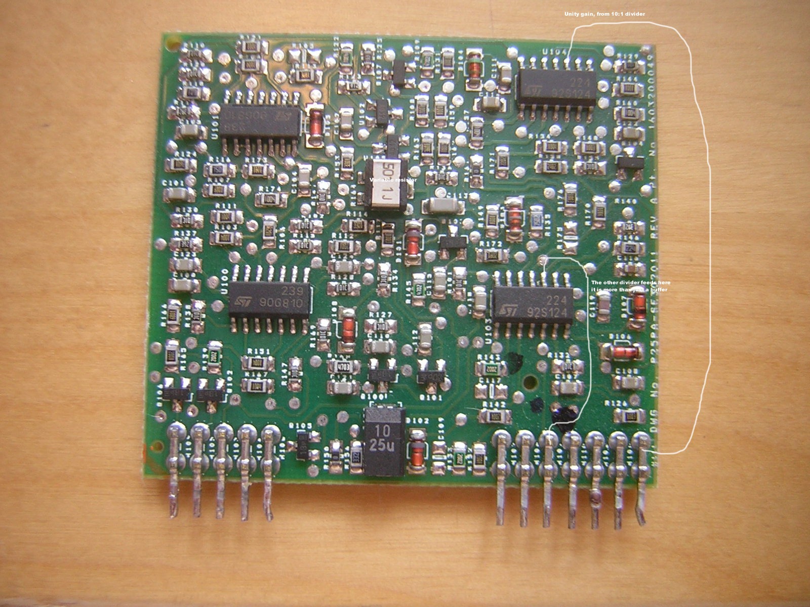
501 1j in the middle od the daughter board is a variable resistor, I may twiddle it if I'm feeling brave.
All I know about the daughter board...Err, from memory :blush:
Note to self: Work out how to do thumb nailsLast edited by ecat; 01-08-2010 at 12:01 AM.
-
01-08-2010 #56
Last Activity: 08-02-2014
It's alive!!! Muhahahahhahaha
Whenever I put something back together I'm always delighted if it still works, from that point everything else is gravy :)
Ok, in fixed mode I now have 47v output :naughty:
First attempt was across R12, I don't know what it is supposed to do but it doesn't affect the fixed mode voltage.
Second attempt I used 9k4 in parallel with R34 and the result is close enough to my calculations. Always a good sign. Why start with 9.4k? Simple, I found a bag of 4k7s.
Calculations:
Top divider resister is 9.1k
We are changing the value of the divider resistor, call this value x.
Desired output voltage is op
Ratio is the ratio of the divider
These calculations are based on k ohms
op = 4.29 * Ratio
Ratio = op / 4.29 : Required Ratio
Ratio = (9.1 + x) / x
x = 9.1 / (Ratio - 1) : Required resistance
As we are creating the value x by placing a resistor in parallel with the existing 1k resistor we need a bit more maths. Lets call the parallel resistor rp.
x = 1 / (1/rp + 1/1)
rp = x / (1 - x)
N.B. In the case of THIS power supply, the existing resistor is 1k. As x is the value resulting from paralleling a second resistor, x will always be less than 1.
Ok, now to work through for my measured 47 volts:
47 = 4.29 * Ratio
Ratio = 47 / 4.29 = 10.956
x = 9.1 / (10.956 - 1) = 0.914
rp = 0.914/(1 - 0.914) = 10.63
Hum, 10.63k is not the 9.4k we expected, lets work the calcs the other way:
rp = 9.4
x = 1 / (1/9.4 + 1/1) = 0.904
Ratio = (9.1 + 0.904) / 0.904 = 11.07
op = 4.29 * 11.07 = 47.49v
Less than 0.5v difference, maybe my calcs go wrong somewhere or my meter is worse than I thought, but I think the result is close enough.
-
01-08-2010 #57
Last Activity: 17-03-2017
yes... but it could equally be setting the current limit! might be worth twiddling....
I've identified all the parts on the daughter board with the except of U102 and U105 which are just above the variable resistor, marked A012. All the other transistors on the board are generic NPN (1Bp = BC846) and PNP (3Dp = BC856) but these are designated like ICs - I have a suspicion they might be band-gap current sources or something...i dont think they are mosfets as these are designated 'Q' types elsewhere and diodes are 'D' (there are 6 generic small signal types and 2 zeners).
I've imported the diagram into Visio and populated it... now just putting in the links.... see attached WIP...
-
01-08-2010 #58
 Last Activity: 11-11-2023
Guys, all this electrickery is terrifying! :confused:

Keep up the good work!
-
01-08-2010 #59
Last Activity: 08-02-2014
That's some mark-up irving, thank you :)
It could be the current limit, it could be almost anything, lol. I'm just looking at the system as a black box controller and I'm especially trying to avoid that daughter board, I suspect it may be more clever than I am ;)
The current limit should be quite easy to trace. R30 is used to sense the current, this feeds to daughter board pin 7. I have no idea what d13 is doing in there.
That big daughter board VR has me puzzled, but you know what curiosity does to cats and ecat is especially suspicious of the intentions of the 400vdc lines.
@Tom,
Thanks for your support.
k, I'm off to kill some zombies :)
-
11-08-2010 #60
Last Activity: 11-04-2011
Hi,
How long it takes when yours power supply arrived?
I ordered a supply three days ago and nothing yet happened.
Usually ebay seller has sent message when you buy something, but he has´nt sent anything.

 Reply With Quote
Thread Information
Users Browsing this Thread
There are currently 1 users browsing this thread. (0 members and 1 guests)
Similar Threads
-
can I have my power supply in a seperate box?
By nobby in forum General ElectronicsReplies: 1Last Post: 12-06-2013, 11:33 PM -
Minimal-cost Power Supply Strategy - Repurpose Laptop Power Supplies
By LoveLearn in forum General ElectronicsReplies: 0Last Post: 25-01-2012, 09:29 PM -
FOR SALE: 50V 20A Power supply
By Jimmybristol in forum Items For SaleReplies: 8Last Post: 30-05-2011, 11:01 PM -
12V Fan off 230v power supply ?
By Buba b in forum General ElectronicsReplies: 5Last Post: 02-03-2010, 09:51 PM -
power supply
By hitmythumb in forum General ElectronicsReplies: 6Last Post: 21-06-2009, 10:27 AM

Bookmarks