
Threaded View


-
17-07-2016 #11

 Last Activity: 06-07-2022


Hi Dave,
I have taken photos as part of my advert so thought I would share just to give you ideas.
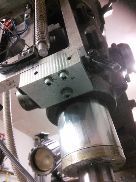
Started off with a plate that I flattened and cut out holes to allow access to the tramming bolts and the quill front. Used the two steps on the front of the head as a means of alignment but found they were about 0.5mm off plain. So I have shimmed the one of the flats.
Behind the ballnut you will make out a socket cap screw that engages with the actual casting where I drilled and tapped an M8. The box above I made using some scrap piece of 6mm plate and practiced my aluminium welding.

The ball nut mount is made up of two parts that sort of dove tail into each other. This part is made of mild steel and I was well chuffed to get the clearances between the parts to 0.05mm. The two parts are held together by the M8 socket cap just behind the ballnut. I could thus home the Z, undo the screw and use the quill manually.
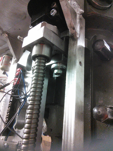

The mounting plate is secured on the bottom through the old feed hole in the front using a top hat boss which allows me to not lose too much quill travel.

On the side, since the quill powerfeed is not used any more, I have used the holes to mount a side brace. If you notice there is a small M4 screw just under the elbow of the pressure regulator, this is to tension the belt of the motor. I have built this kind of tensioner in all the axes of my machine.

Yours is bound to look prettier of course, hope you got some ideas though.https://emvioeng.com
Machine tools and 3D printing supplies. Expanding constantly.

 Reply With Quote
Thread Information
Users Browsing this Thread
There are currently 3 users browsing this thread. (0 members and 3 guests)
Similar Threads
-
Milling machine CNC conversion - keep hand wheels for manual operation?
By birchy in forum Milling Machines, Builds & ConversionsReplies: 5Last Post: 23-10-2016, 08:29 PM -
Manual autochanger problems.
By Saracen in forum Lathes, Lathe Rebuilding & ConversionsReplies: 1Last Post: 05-02-2015, 01:14 AM -
WANTED: Centec 2A manual
By Web Goblin in forum Items WantedReplies: 0Last Post: 03-09-2012, 09:56 AM -
Translating the manual
By Robin Hewitt in forum Moulding MachinesReplies: 22Last Post: 01-09-2012, 01:21 PM -
Bridgeport Conversion
By Tony Goodwin in forum Bridgeport Milling MachinesReplies: 0Last Post: 08-08-2011, 08:11 AM

Bookmarks