
Thread: Fill in my knowledge gap :)
-
05-08-2016 #31

 Last Activity: 1 Day Ago


 Originally Posted by routercnc

While we are here. Just in tune with your calculations /that i will have to save somewhere/ - i needed a couple of times to calculate a V cutter flute length /FL/. Reason was i have V cutters that cut deeper than their flutes, a mix between V cutter and spiral flute mill, where the flute ends at shank width. Wow, it took me some time to figure how to calc these so i could draw them properly in program. Properly means exactly without any errors.
I read here how to calculate the flute length Link,
the formula for sides of Isosceles Triangle, so i came up with FL=((shank diam - tip diameter)/2)/cos((180-vertex angle)/2)
-
05-08-2016 #32

 Last Activity: 30-12-2023
 Nice one mate, can I just ask, where did you get the Haimer from as I was also considering getting one? Originally Posted by Davek0974
Also, John Saunders has a good channel which shows a lot of tutorials for F360, Fusion Friday I think they`re called
https://www.youtube.com/user/saunixcomp/videos
-
The Following User Says Thank You to needleworks For This Useful Post:
-
05-08-2016 #33
Last Activity: 09-02-2022
Got it from WNT, came next day ;)
-
05-08-2016 #34
Last Activity: 30-12-2023
Not being a lazy sod, but just had a look and can`t find any probing tools !! you don`t happen to have a link do you mate?
-
05-08-2016 #35
Last Activity: 09-02-2022
Here you go, i got the HQ unit...
https://www.wnt.com/uk/search-result...335&no_cache=1
-
05-08-2016 #36
Last Activity: 2 Hours Ago
Real example. I'm a bit embarrassed to talk about it because it seems so trivial compared with the usual projects described, but never mind. My wife wanted some simple dividers to go in some plastic crates to separate whatever it was she was storing. I had some 3mm ply sitting around, so planned to use that. Could have cut flat panels with sloping edges to fit the crates, but wanted something a bit clever. So I added flanges to the divider plates, with tabs on the dividers fitting into tight-fitting slots in the flange pieces. Because of the tapered sides, I could have calculated dimensions but that would have been time-consuming so I drew the dividers with tabs on, then drew the flanges and could "cut out" the slots where the tabs went, and because this was all done in F360, I knew that all the bits would fit - which they did, and they fitted the boxes nicely. I could then take the individual components and lay them out for CAM and 2D cutting. I could have done it in VCarve but, as I say, that would have needed me to do some sums to work out tab and hole positions. As it was, I've no idea of the actual dimensions of the tabs but I could use F360 features to get them equi-spaced, match tab/gap spacing, etc, with very little thought or work on my part. I would use VCarve, for instance, for making an engraved sign where all the work is 2D and the CAM really good for that kind of v-engraving. Horses for courses. Originally Posted by Davek0974
For this kind of work, though, there is one small point where VCarve beats F360 hands down, and that is generating corner fillets for the holes to take rectangular tabs. You can do it in F360 with an add-on, but it's so trivially easy in VCarve. In fact, for my dividers, I ended up exporting DXFs of the panels and flanges and doing the CAM in VCarve. I'm not proud...
-
06-08-2016 #37
Last Activity: 09-02-2022
Yes, i love the T-Bone and Dog-Bone fillets in Aspire, use them a lot.
Your example was good - I had only been looking at a single part - maybe THAT is where things change to to F360 - when you want to make assemblies?? As you said, I would have measured the inside of the crates, calculated angles, positioned my tabs, then positioned the slots and then made each part with no knowledge that they will actually fit together properly.
The reason i had not seen this is that my stuff has all been single parts so far or just two parts that fit together easily. One other aspect is that with F360 the customer can see the part before you CAM it, in Aspire you have to CAM it and run the simulator to reveal the parts. In SheetCam you can do neither as there is no 3d viewer, but it is hands-down my favourite program for the plasma cutter and also for very simple mill stuff.
I guess i will plod on with F360 in my spare time, my main issue is that it is cloud based and i have a dislike for cloud apps. But as its free for home use, i will live with that i think :)Last edited by Davek0974; 06-08-2016 at 08:37 AM.
-
06-08-2016 #38
Last Activity: 2 Hours Ago
When you are comparing products like Aspire/VCarve and F360 which include both CAD and CAM modules, you do have to be careful to compare like with like. The Vectric CAM stuff is really easy to use, although it might not have quite all the features of F360 but which are more difficult to find and configure - there are so many options and parameters! However, I compare the CAD part of VCarve (and TurboCAD, which I used to use) to a power-operated drawing board. Very accurate, precise, etc, but a real pain if you want to change something in a design which is going to affect other parts of the design. Often easiest to delete and start again. F360, on the other hand, is like a power-operated "back of the envelope". Once you get used to the very different starting point - you literally sketch something that is kind-of what you want, then go back in and add critical dimensions where you have to and constrain and link other relationships wherever you can - suddenly you find that you have something where you can change history. Want to increase a dimension on something you did at the beginning of a drawing? Just change it, and watch the knock-on effects ripple through everything that you did after that point. I've done demos of F360 a few times, and I usually draw a simple bracket made from two plates joined at 90deg. I show how you position mounting holes in the edge of one piece and how the clearance holes in the other are linked - change the first piece and the second changes with it. Magic, once you're used to it!
-
The Following User Says Thank You to Neale For This Useful Post:
-
06-08-2016 #39
Last Activity: 1 Day Ago
A parametric CAD will always shine, when later changes are needed. Aspire will shine in a workshop environment for everydays stuff, simple jobs, signs, carving. The fluidity when making signs or carvings is uncomparable. Try that in other program and you will soon get frustrated.
One main thing that i start to miss very much in Aspire is trochoidal toolpaths. Its annoying and i see no reason why they don't include that, given its price. Now i am playing around with Estlcam which is 50euro and has that function. By the way I highly recommend that program as very intuitive and capable and am thinking to buy a license.
I could make the same in NX9 CAM part but i have to spend 1h deciding 50 details just for a simple pocket. Hence i start to need a simple CAM for the trochoidal toolpaths. That's why i am testing now the EstlCam. This program has one little very annoying detail that if fixed could be a serious contender even for Aspire. I am planning to contact the maker. Its that you don't see a toolpath list window like in other programs, but instead have to simulate the cut to see the various toolpaths and their order. Fix that and there will be a wow prog for 50 euro.
-
06-08-2016 #40
 Last Activity: 23-09-2017

Aspire can do some 3D work.
This was done in Aspire
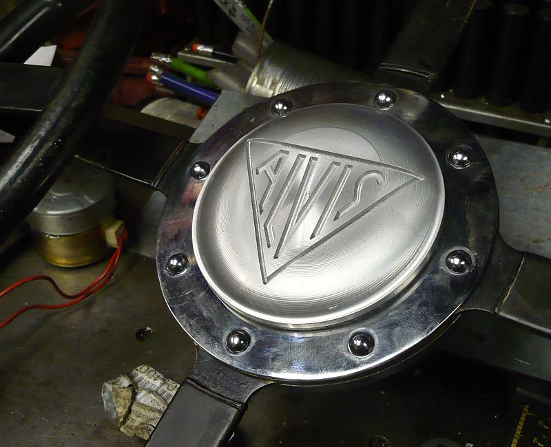 but for parts with curves, think a mobile phone mold etc you need 3D / fusion 360
For most part they are just built up from 2 1/2D parts that Sheetcam can handle fine.
Carry on as you are and jump later if needed. the time for the learning curve is far better spend doing what you can do.John S -

 Reply With Quote
Thread Information
Users Browsing this Thread
There are currently 1 users browsing this thread. (0 members and 1 guests)
Similar Threads
-
how to fill/paint letters that i have engraved in wood ?
By cockneyrebel in forum Wood Finishing Tips & TricksReplies: 11Last Post: 26-03-2013, 11:21 PM

Bookmarks