
Thread: fresh start 8x4 build
-
26-09-2016 #21

 Last Activity: 19-01-2024


 Was not my intention to slap ya mate.! . . . . I'll keep stum if you like.?
 Originally Posted by reefy86

-
26-09-2016 #22
 Last Activity: 18-01-2026
I slapped my own face for being dumb I meant lol
-
27-09-2016 #23
Last Activity: 18-01-2026
update :)
-
27-09-2016 #24
 Last Activity: 20-04-2020
I love this forum. Had planned to make my x cars for the gantry in a similar way. After reading this I have to rethink to ;)
-
28-09-2016 #25

 Last Activity: 15-04-2024

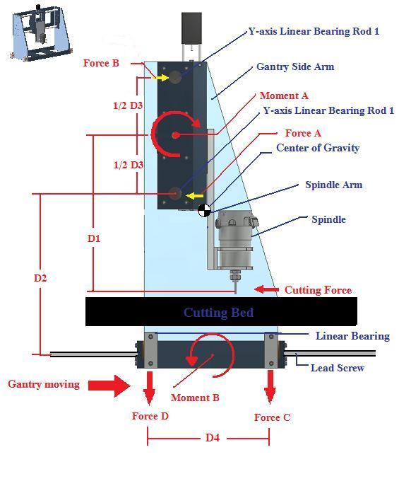
Or all this is just an indication that at the end you fill finish with too much spindle Overhang on gantry. My criteria is that in a good design, when looked from side, the bit should stay in the bearing spread or the sall called gantry side legs. Or at least not be too far in front of it. I don't see what you will be saving here? 5cm of rail?
-
28-09-2016 #26
Last Activity: 18-01-2026
you mean keeping spindle bit more or less as centre to the bearing blocks or centre to the side plates as much as possible?
-
28-09-2016 #27
Last Activity: 15-04-2024
I mean D4 to be so long /260-300mm/ that router bit stays inside it. Its called -overhang/ how far from X rail is the spindle nose. There is center of gravity also. The nearest the bit to the center of gravity, the better. Ideally all should be designed so that is perfectly balanced .
you could read basic info about forces there http://www.cncroutersource.com/do-it...NC-router.html
But you could do it out of this concept as you like, if using Hiwing 20 rails and carriages. They are so strong that overhang is not a problem. Just i like things to be perfectly balanced and engineered
-
The Following User Says Thank You to Boyan Silyavski For This Useful Post:
-
28-09-2016 #28
Last Activity: 18-01-2026
thanks boyan, from spindle nose to x axis is 151mm, d4 as you describe is 215mm.
Ash
-
29-09-2016 #29
Last Activity: 18-01-2026
im hoping im slightly correct but are these images right?
-
29-09-2016 #30
Last Activity: 15-04-2024
Hi, just answered your PM but could not upload pictures there. Just saw what you have posted as images .
In short - NO. Dont despair, but this is not right. You will figure it out :-).
Lets see:
This is how its the right way:
Look at the ideal/ my machine is on the extreme side so not necessary so much / but hence is nice for illustration:
Also this is the correct way, i would say the perfect way for the Z plate, so its naturally reinforced by the rails and the plates at the back and
And finally, design so much travel and space brackets so that at lowest position of Z axis the spindle still reinforces the Z plate. Ignore that the spindle is small , because its small one 0.8kw and Z axis real travel is 180mm . NOrmal 2.2kw or 3kw spindle is much longer. This just to illustrate eventual max. Position:

 Reply With Quote
Thread Information
Users Browsing this Thread
There are currently 1 users browsing this thread. (0 members and 1 guests)
Similar Threads
-
CONVERSION: my build from the start
By h4ppy-chris in forum Conversion Build LogsReplies: 126Last Post: 03-08-2020, 10:22 PM -
Well here we go again, start another build
By D-man in forum Gantry/Router Machines & BuildingReplies: 5Last Post: 22-01-2014, 09:59 AM -
Build log when to start posting on this site
By ramsbury in forum General DiscussionReplies: 6Last Post: 15-01-2014, 10:43 AM -
NEW MEMBER: Hello all, finally ready to start a build log.
By Iwant1 in forum New Member IntroductionsReplies: 11Last Post: 25-12-2012, 06:03 PM -
A few questions before I start my build
By eclassic in forum General DiscussionReplies: 0Last Post: 11-07-2011, 10:54 PM

Bookmarks