
Threaded View


-
16-11-2016 #6

 Current Activity: Viewing


I was going to post about some of the intricacies of the machine wiring, however I'll stick with controllers for now.
.
Now I've got all the boards, I need to mount them.
The old computer, which was bolted to the control cabinet door was removed, and a suitable bit 3mm aluminium sheet was cut to size. The reason for 3mm, is it's strong enough to bridge pretty big areas with minimal support, and thick enough for drilling/tapping for directly mounting items. Thinner would be marginal for drilling/tapping, and thicker just adds expense for little to no benefit.
.
First step once the sheet had been cut and drilled for mounting to the cabinet door, was to play tetris with the various boards-
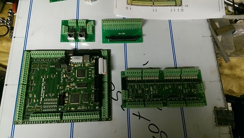
Which highlighted the first non-ideal thing. My lovingly designed and built differential driver board would of been better had the in/out RJ45 jacks been the opposite way around. As it stands, it just means I need to make the cables a bit longer and they'll cross.
If noise was to be a problem, I choose the shielded jacks so shielded cable could be used if needed.
.
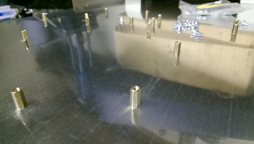
So now things are positioned, it's a case of marking out all the various holes, followed by drilling and tapping all the required holes.
When doing this, is I like to drill the required holes slightly undersized. Everything mounts via M3 stand-offs, and Standard/Course M3 has a pitch of 0.5mm, so the ideal tap drill size is 2.5mm. Instead I use a 2.4 or 2.3mm drill, as it allows a bit margin for if the drill isn't perfectly straight, or isn't drilling perfectly on size.
I then tap using a M3 spiral flute drill in the cordless drill, before hoping my marking out and drilling was on target-
.
Managed to only get one hole slightly off, but thankfully it was for the IDC breakout board, so a quick file and everything bolted together perfectly-
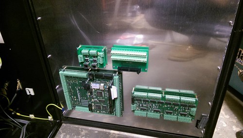
Something I like to do here, is although I fitted all the boards on the bench, I never tightened the screws until I had the plate bolted to the cabinet door. My reasoning for this is to minimise the amount of strain placed on the PCBs should the back plate twist any when finally bolted down.
.
And you may be wondering why the IDC breakout board has been added. I may need to use a couple of the feeds provided by the Kanalogs IDC header, so it's far easier to fit the board and not need it, rather than fitting it later and risk getting some swarf somewhere I really don't want to.Avoiding the rubbish customer service from AluminiumWarehouse since July '13.
-
The Following User Says Thank You to m_c For This Useful Post:

 Reply With Quote
Thread Information
Users Browsing this Thread
There are currently 5 users browsing this thread. (0 members and 5 guests)
Similar Threads
-
Denford Triac - Help
By mikeadams1985 in forum Denford MillsReplies: 1Last Post: 12-01-2017, 10:06 AM -
FOR SALE: Denford Triac CNC PC
By ricey3 in forum Items For SaleReplies: 6Last Post: 10-01-2017, 01:39 PM -
Denford Triac VMC
By fidia in forum Milling Machines, Builds & ConversionsReplies: 6Last Post: 19-08-2016, 08:18 AM -
Help Denford triac p.c.
By mikeulike in forum Denford MillsReplies: 3Last Post: 02-06-2015, 03:59 PM -
WANTED: Denford Triac
By edwardsjc in forum Items WantedReplies: 13Last Post: 20-08-2012, 08:17 AM

Bookmarks