
Threaded View


-
04-12-2016 #10

 Current Activity: Viewing


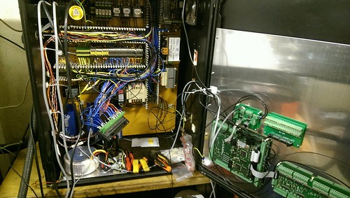
Wires. Wires. Wires everywhere.
.
.
So where do you start with wiring a retrofit?
For me it's always the power supplies, and related circuitry.
First up was a switched mode 5V DIN rail mounted PSU to power the KFlop/Kanalog. Nice and simple, it gets a permanent live feed whenever the machine is switched on. It can just be seen on the lower DIN rail just to the left of the original cream coloured 24V supply.
.
Next is the big linear supply for the steppers, however it relies on being controlled by the E-stop circuit. As is best practise when powering stepper drivers, you only ever switch the input side, so a suitable contactor was added, controlled via the E-stop circuit, which is at the very left of the lower DIN rail.
Something I struggled with while initially deciding on how to handle E-stops and enabling on earlier retrofits, was what should be hardware controlled, and what should be software controlled. The advice I got, was keep them distinctly separate. Two main reasons for this, first is it avoids a race situation, and two, should something go wrong, you should know if it's due to a hardware or software problem.
For those not familiar with a race situation, it's more a programming term, where due to two interdependent conditions, they both get stuck because of each other.
In terms of what I'm discussing here, if you were to rely on the control/software activating the E-stop circuit, how would you initially activate it, given the control would see it as tripped due to the fact the control hasn't activated it?
.
This is where drive enable circuits come in.
The E-stop circuit cutting power should be seen as a final way to kill motion in the event of controller failure, as it will usually take a second or two for the power to drop low enough for motion to stop.
By using the enable signal to stop motion, motion should stop quicker, although by removing the enable, the motor will usually be left to freewheel to a stop. However on a stepper driven machine this is not usually a major issue.
Off course, as I'm using a KFlop, this gives me the ability to handle this aspect however I like. This gives me the option to implement a minor delay between stopping the step/dir pulse stream, prior to the enable signal being removed.
I end up with a flow like this-
1) E-stop circuit deactivated (I.e. E-stop button pressed, limit switch hit)
2) Power disabled and KFlop notified E-stop triggered simultaneously
3) KFlop immediately stops motion signals
4) 200ms later KFlop removes enables
5) Residual power drains
.
You may be wondering why I'm happy to rely on the KFlop in this way, but it's because it will do exactly what it's programmed to do. It's not like a PC which may hang due to myriad of things. At this level of operation, it's programmed as a microcontroller, with no influence from the PC. Once the system has been initialised, you can unplug the PC, and the KFlop will still react in the same way. Even if it wasn't, the removal of power will still stop motion eventually.
.
Off course, once you get into servo drives, you have other considerations, like do you really want to cut power instantly (cutting power will usually result in drives faulting and motors freewheeling to a halt), servo drives usually have the option of implementing a Stop signal, which when triggered will cause the drive to stop the motor as fast as possible.
.
The only addition I did make to the original E-stop circuit, was the Kanalog board has an enable signal, which goes active once the KFlop and Kanalog board have fully powered on. The reason for this, is during initial power up, prior to the KFlop establishing communication with the Kanalog board, the Kanalog outputs will be in an indeterminate state (i.e. they are not guaranteed to remain deactivated). I simply use the signal, which is a relay driver capable output, to power a relay, which in turn is part of the E-stop circuit. For those familiar with parallel ports/Mach/LinuxCNC, it can be thought of as a charge pump circuit.Avoiding the rubbish customer service from AluminiumWarehouse since July '13.
-
The Following User Says Thank You to m_c For This Useful Post:

 Reply With Quote
Thread Information
Users Browsing this Thread
There are currently 2 users browsing this thread. (0 members and 2 guests)
Similar Threads
-
Denford Triac - Help
By mikeadams1985 in forum Denford MillsReplies: 1Last Post: 12-01-2017, 10:06 AM -
FOR SALE: Denford Triac CNC PC
By ricey3 in forum Items For SaleReplies: 6Last Post: 10-01-2017, 01:39 PM -
Denford Triac VMC
By fidia in forum Milling Machines, Builds & ConversionsReplies: 6Last Post: 19-08-2016, 08:18 AM -
Help Denford triac p.c.
By mikeulike in forum Denford MillsReplies: 3Last Post: 02-06-2015, 03:59 PM -
WANTED: Denford Triac
By edwardsjc in forum Items WantedReplies: 13Last Post: 20-08-2012, 08:17 AM

Bookmarks