
-
12-02-2017 #31

 Last Activity: 1 Week Ago


Things like this would be nice to copy out to a tutorial section for future reference as stickies
..Clive
The more you know, The better you know, How little you know
-
12-02-2017 #32
 Last Activity: 19-01-2024

Not sure if this a good advert for Kflop or not.? Certainly not for the beginner.! But well written.
Last edited by JAZZCNC; 12-02-2017 at 11:27 AM.
-
12-02-2017 #33
Last Activity: 8 Hours Ago
It's certainly not a simple bit of kit, however I have seen a few complete beginners manage to get some quite complex systems up and running, with not that much help. It's one of those things, that if you want to learn how to get it working, you will, and you could say the same about most controllers if you've got no experience.
 Originally Posted by JAZZCNC

Saying that, this is one part of setting up that would really benefit from a video showing the actual process, as once you know the process, it's not that hard.
There are a few Dynomotion videos showing specific parts, or for specific boards. The KStep Introduction video, from 3:55 onwards shows the software process - https://www.youtube.com/watch?v=pW-9fDLAn2sAvoiding the rubbish customer service from AluminiumWarehouse since July '13.
-
12-02-2017 #34
Last Activity: 04-01-2026
Well, I use Kflop and I was a complete beginner, my only coding experience was with Arduino which operates on a kind of simplified version of C.
I first found it daunting. But I will say this, you don't really need to know the C language to make it work, you just need to apply a bit of common sense and spend time reading forum posts and reading the instructions. I requires real determination and patience and I fear that a lot of people will give up, which is a shame because it's a fantastic controller card.It's by no means a plug and play card.
My breakthrough was when a friend sent me a basic set up file for the three motors. Very basic, but enough to get the motors going. In fact, Kmotion already includes a simple configuration file that can be used. But it is a convoluted program, you have to go from one window to the other and then back again. For instance, if the axes are disabled due to an e-stop, you can't switch them back on from within the CNC program, you have to open another program to enable the axes back again. They should amalgamate the two main programs (KMotion and KMotionCNC) into one.
But, like a lot of applications, suddenly it all starts to click and make sense, and it is not difficult to add some lines of code to the basic init file as you build up the system.
There are quirks, for example, you don't upload to the drive, you download. To reverse motor direction you set up your Gain to -1....then most of the program settings are calculated in inches, although you can work in metric when it matters.
It is a very powerful and very stable controller, but it could do with some simplification for the novice, without losing the ability of tweaking and adding once you gain the experience. I think most Kflop users have needed some help at the beginning either from the very helpful owner or from other kind users.
As for Dean's comment, he is spot on, you need to put yourself on the side of the novice to understand that even the very detailed information in M_C's post is just too daunting and a lot of people will say, the hell with it, I want a controller that works first time without all that coding palaver!
Edward
-
14-02-2017 #35
Last Activity: 8 Hours Ago
Arduino uses C++ (C plus plus), which is a higher level version of C. The other major version of C is C# (C sharp), which is a higher level yet. Originally Posted by Edward
However they all use fairly similar coding techniques/layouts, so experience of any is a benefit.
KMotion is solely for configuration. KFlops are not solely designed for CNC use, and KMotion contains the functionality to configure and program KFlops to run standalone, or via software.My breakthrough was when a friend sent me a basic set up file for the three motors. Very basic, but enough to get the motors going. In fact, Kmotion already includes a simple configuration file that can be used. But it is a convoluted program, you have to go from one window to the other and then back again. For instance, if the axes are disabled due to an e-stop, you can't switch them back on from within the CNC program, you have to open another program to enable the axes back again. They should amalgamate the two main programs (KMotion and KMotionCNC) into one.
KMotionCNC is just a PC program to use the KFlop as a more conventional CNC controller. The full source code is provided, so if you really want, you can edit the source and recompile it.
Dynomotion provide a pretty comprehensive library for creating your own software, along with example programs for all the possible software interfacing methods (A quick scan of the directory shows Virtual Basic, C, C#, LabView and Python). The only things that are not publically provided, are the base programming for the KFlop, and the source code for the firmware and the various DLLs/dotNet framework which provide the software interface.
The key to setup, is to get a basic init.c file created as quickly as possible, then add to it as you get things configured. Taking your example about re-enabling things after an EStop, you could create a very simple init.c that simply turns outputs back on. I didn't have that problem on this machine, as during setup the EM806 drives default to enabled, but it would be a simple case to add a SetBit(xx) command to your init.c to activate the output for your drive enable.
I'll expand more on the general C program framework I use for my machines when I get time, as all I've posted so far is the bare minimum to get machine movement. Things have expanded quite a bit since that basic file, as E Stop monitoring code and tool changer code has been added. I'll also discuss how I use the multiple program threads.
The whole download/upload thing is actually quite common in the programming world, but there is no hard and fast way to know. My day job is dealing with vehicle diagnostics, and it can be a nightmare. Ford programming software you download software updates, and upload configuration data to ECUs. GM/Vauxhall you upload software to ECUs and store configuration data. Mercedes you download updates to ECUs, and then set parameters.There are quirks, for example, you don't upload to the drive, you download. To reverse motor direction you set up your Gain to -1....then most of the program settings are calculated in inches, although you can work in metric when it matters.
The best way to think of it is the KFlop is the server, so you're uploading to it, and downloading from it when dealing with motor parameters. Off course, then you download C programs when you want to run them..
The whole imperial thing is my biggest gripe with KMotionCNC. It's natively written around inches, so if you are going to be changing between metric and imperial, you have to allow for the fact that the tool table is unitless.Avoiding the rubbish customer service from AluminiumWarehouse since July '13.
-
17-02-2017 #36
Last Activity: 8 Hours Ago
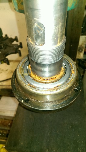
So getting back to the mechanics, the spindle was stripped, and rebuilt with new bearings and fresh grease. I only took one photo of it, which is this one, showing the spindle removed, but the lower bearing, and lower bearing retainer still on the spindle.
The process goes something along the lines of-
Remove drawbar cylinder.
Unbolt top support bearing and housing, and extract using bolts into the threaded holes provided for the purpose.
Remove spindle motor and drive belt (you have to unbolt the motor to get the belt of)
Remove notched adjustment nut, along with locking tab ring.
Unbolt the lower spindle bearing retaining/seal plate.
Knock/press the spindle down out of the head assembly.
Pull the lower bearing of the spindle.
And reassemble in reverse.
After reassembly, you need to preload the bearings. The method used by Denford was to adjust by feel.
Now as I deal with things like this occasionally, I've got a reasonable idea of how a preloaded bearing should feel, but I'll give some tips for those who've never done it before.
Once you have the spindle assembled, with the adjustment nut on, nip the nut up. Then using a hammer and punch on the top face of the nut, give it a tap at various points around the nut. Nip the nut up again.
Now using a block of wood on the face of the spindle, give it a couple taps upward, before seeing if you can get anymore movement on the nut.
Repeat a couple times until you're happy things are settled, with no more movement on the nut.
What this does, is help ensure everything is seated correctly. Given the interference fit of parts, it's very possible that you could preload the bearings, but without something seated correctly. What that would mean, is that you rebuild everything, and then after a period of time (it could be after a few minutes, or even a few months), the whatever it is will settle in, your preload disappears and you end up with a load of spindle run out, where it's flapping around in the bearings.
At this point I gave the spindle a good few spins to help work the fresh grease out from the bearing tracks.
Now taking a DTI mounted on the head (so any movement in slides doesn't affect the reading) and set against the side of the spindle, using a best guess effort as too how much pressure the spindle is likely to see, I grab the top of the spindle and pull/push it in the direction of the DTI needle.
I then adjust up the lock nut until I'm getting minimal movement. I spin the spindle a few times, give things another tap with the hammer/punch/block of wood, and recheck. Once no more adjustment is needed, I spin the spindle by hand. I then adjust up the nut until I feel a very slight bit of springiness just as the spindle starts to move. Once again, I give everything a tap, and recheck. Once I'm happy, I bend a locking tab into a notch.
The real proof in whether you've got it right, is in the running.
Once you get the motor back on, you should run the spindle at a lowish speed (I opted for about 500rpm) for 10-15 minutes to let the grease work it's way out from the bearing tracks, while also monitoring the spindle temperature.
If you run the bearings too fast too soon, they can slide on the grease, which results in premature wear and even causing flat spots on the bearings, which will lead to vibrations and poor cutter finishes.
If everything sounds OK, gradually ramp the speed up, allowing maybe 5 minutes at every step (I went up in 500rpm steps), while monitoring the temperature. If you've got the preload within acceptable limits, after an hours running the spindle/housing should of warmed up, but you should still be able to keep your hand on it. If at any point you can't keep your hand on it, you've got too much preload, so stop it and slacken the adjustment nut of a notch. If on the hand it barely warms up, you've not got enough preload, which means you're most likely going to get a rubbish finish on parts as the spindle/cutter deflects while cutting.Avoiding the rubbish customer service from AluminiumWarehouse since July '13.
-
The Following 2 Users Say Thank You to m_c For This Useful Post:
-
19-02-2017 #37
Last Activity: 8 Hours Ago
Now basic machine movement was possible, the next step was the tool changer.
First thing was to wire up the various sensors and relays, which brings me onto the subject of the possible methods for wiring up such things.
Do you switch the positive, or negative side of relays/solenoids?
As I'm using a Konnect board which has individual opto-isolated outputs cable of switching a fairly substantial load for an interface board (250mA @ 30V max), it gives a good amount of flexibility.
However, some controllers will have output banks grouped, and sharing positive supplies (likely to be described as PNP outputs), or sharing a negative supply (NPN style outputs).
Either will work, but switching the positive feed does usually provided an extra layer of safety. Should a wire short out to ground i.e. chaffs through on the chassis anywhere, then the output should just stop working. It may damage the output chip/transistor/FET on the board due to overloading the output, but at least whatever that output controls should stop working.
The flip side is if you were to switch the negative side, and the wire was to short out, whatever that output controlled would remain active.
And as we're on outputs, I'll cover inductive loads. An inductive load is pretty much anything that involves some form of electromagnet, which covers solenoids, relays, and motors.
These all provide a couple problems for controlling them. First, they will usually cause a surge of current on activation, usually followed by a voltage spike on deactivation.
A typical 250mA output will usually quite safely handle a standard icecube sized relay (IIRC they have a constant coil consumption of around 70mA at 24VDC). The switch on spike will be multiple times that, but for CNC use, this is the size of relay expected to be used for interfacing purposes.
However the bigger problem is during disconnection. When you disconnect a relay coil, the magnetic field not only quickly collapses, but as the solenoid moves back (remember a relay is essentially a solenoid operating a spring loaded switch), it also affects the magnetic field. Uncontrolled, this sudden change in magnetic field will cause a voltage peak of several times the rated relay coil voltage, with a reverse polarity of the voltage that was previously applied.
This surge can very quickly kill electronic outputs, but not only that, it will produce a spike of electrical noise.
The solution is simple. You add a reverse fly back protection diode to the relay coil terminals. This doesn't have to be anything fancy (I use 1N4007 - 1A 1000V rating as that's what I usually have in stock), and you connect it so that the cathode (end marked with a ring) is on the positive side of the coil. It should also be mounted as closely to the relay as possible, which is why they are rarely incorporated into the interface board.
During normal power, the diode does nothing, but when power is removed, and the reverse voltage spike starts to build up, the diode causes the energy spike to recirculate through the relay coil, where it will safely dissipate.Avoiding the rubbish customer service from AluminiumWarehouse since July '13.
-
The Following User Says Thank You to m_c For This Useful Post:
-
19-02-2017 #38
Last Activity: 8 Hours Ago
So onto getting movement from the toolchanger.
I'll start with a short video showing that it does indeed function -
I'm sure toolchangers initially challenge the best programmers, but as with all things, you just need to figure out the process required to make it work, then convert that into some form of code that your controller of choice will understand.
First is working out the process. As at the time I had a Denford Novamill running on Denford's VRMilling software, I had access to the machine files for all their modern machines, which includes the Triac.
Buried in the relevant Triac file, were all the macros for running a fully kitted out Triac, including the toolchange code-
The official language is Mint, which is specific to Baldor/Denstep controllers, but it's very Basic like, and I'm sure by reading through it, most people will be able to understand what's going on.Code:REM ~~~~~~~~~~~~~~~ Tool Changer Routines ~~~~~~~~~~~~~~ #ArmIn GOSUB SpindleStop IF !comms(10) THEN RETURN : REM ignore it if we're none ATC IF !(OUT & 1) DO : REM Check spindle is stopped OUT3 = 1 : REM Switch the solenoid REPEAT : REM Wait for the IN switch (inverse logic) UNTIL !IN0 OR STOPSW WAIT = 500 ENDIF RETURN #ArmOut IF !comms(10) THEN RETURN : REM ignore it if we're none ATC OUT3 = 0: REM Switch the solenoid REPEAT : REM Wait for the OUT switch (inverse logic) UNTIL !IN1 OR STOPSW WAIT = 500 RETURN #ArmDown IF !comms(10) THEN RETURN : REM ignore it if we're none ATC IF !(OUT & 1) DO : REM Check spindle is stopped OUT4 = 1 : REM Switch the solenoid REPEAT : REM Wait for the DOWN switch (inverse logic) UNTIL !IN3 OR STOPSW WAIT = 500 ENDIF RETURN #ArmUp IF !comms(10) THEN RETURN : REM ignore it if we're none ATC OUT4 = 0: REM Switch the solenoid REPEAT : REM Wait for the UP switch (inverse logic) UNTIL !IN2 OR STOPSW WAIT = 500 RETURN #DrawbarUnClamp IF !comms(10) THEN RETURN : REM ignore it if we're none ATC IF !(OUT & 1) DO : REM Check spindle is stopped OUT5 = 1 WAIT = 500 ENDIF RETURN #DrawbarClamp IF !comms(10) THEN RETURN : REM ignore it if we're none ATC OUT5 = 0 WAIT = 500 RETURN #CarouselCW IF !comms(10) THEN RETURN : REM ignore it if we're none ATC IF !IN3 OR !IN1 DO :REM If arm is back or down OUT7 = 1 : REM Set Direction Output OUT6 = 1 : REM Set the Power output WAIT = 50 REPEAT UNTIL IN4 OR STOPSW REPEAT UNTIL !IN4 OR STOPSW REPEAT UNTIL IN4 OR STOPSW REPEAT UNTIL !IN4 OR STOPSW WAIT = 40 OUT6 = 0 Pocket = Pocket + 1 : REM Inc the Pocket Counter IF Pocket > MaxPockets THEN Pocket = 1 ENDIF RETURN #CarouselHalf IF !comms(10) THEN RETURN : REM ignore it if we're none ATC OUT7 = 1 : REM Set Direction Output OUT6 = 1 : REM Set the Power output WAIT = 50 REPEAT UNTIL IN4 OR STOPSW REPEAT UNTIL !IN4 OR STOPSW WAIT = 40 OUT6 = 0 RETURN #CarouselCCW IF !comms(10) THEN RETURN : REM ignore it if we're none ATC IF !IN3 OR !IN1 DO :REM If arm is back or down OUT7 = 0 : REM Set Direction Output OUT6 = 1 : REM Set the Power output WAIT = 50 REPEAT UNTIL IN4 OR STOPSW REPEAT UNTIL !IN4 OR STOPSW REPEAT UNTIL IN4 OR STOPSW REPEAT UNTIL !IN4 OR STOPSW WAIT = 40 OUT6 = 0 Pocket = Pocket - 1 : REM Dec the Pocket Counter IF Pocket < 1 THEN Pocket = MaxPockets ENDIF RETURN #toolChange GOSUB SpindleStop if !comms(10) THEN Pocket=Comms(7) : REM store last tool if not ATC IF (comms(7) = Pocket) OR !comms(10) THEN RETURN : REM ignore it if we're already there or none ATC IF !(OUT & 57) DO : REM If atc is back,Up and drawbar safe IF STOPSW THEN RETURN GOSUB ArmIn IF STOPSW THEN RETURN GOSUB DrawbarUnclamp IF STOPSW THEN RETURN GOSUB ArmDown REM Calculate the shortest path... steps = (comms(7) - Pocket + MaxPockets) MOD MaxPockets IF steps > (MaxPockets / 2) DO WHILE Pocket <> comms(7) GOSUB CarouselCCW ENDW ELSE WHILE Pocket <> comms(7) GOSUB CarouselCW ENDW ENDIF GOSUB ArmUp IF STOPSW THEN RETURN GOSUB DrawbarClamp IF STOPSW THEN RETURN GOSUB ArmOut IF STOPSW THEN RETURN ENDIF RETURN REM ~~~~~~~~~ End of Tool Changer Routines ~~~~~~~
The basic process is-
Move arm in.
Activate drawbar.
Move arm down.
Rotate to next tool.
Move arm up.
Release drawbar.
Move arm out.
There are various delays involved at each step, but that's the basic process.
Now with a KFlop, there are a few different ways I could of implemented this, but I'd better explain how a KFlop runs user programs.
KFlop has 7 threads, where separate user programs can be run, each getting an equal slice of time when running (for those interested in the exact details, check here).
This gives you a lot of flexibility. My basic init.c file, that will also monitors things like conditions for E-stops, soft limits, and button presses, runs continually in thread 1 (for those familiar with Mach, think of it like the macropump script).
I then have 3 homing programs (one for each axis), that when activated, each run in their own threads. This means I can start homing in any order, and all axes can be homing at the same time. I'm not restricted by them having to be done in any specific order (I could program that if I really wanted, and I may change to that for simplicity, but I'll stick to separate buttons for easy testing).
What this means, is for the toolchanger, I could simply create a program that runs in it's own thread, and does it's thing. However at some point I want to add external buttons to help with changing/setting tools, which using the separate thread method, would get quite messy, with very similar code being needed in various different programs.
The solution is to incorporate the main toolchange functionality into the main init.c thread that runs permanently, but that introduces a bit of a problem, in that it has to be programmed in a way that doesn't block the main thread execution.
Blocking is something you have to consider for any programming, and I'm sure some people are wondering what blocking is.
Using the tool changer as an example, after the arm moves in and the arm in switch is activated, there should be a 500mS delay before the drawbar is activated.
If you were to program using the following simple method-
(it's not in any specific language before anybody comments!)Code:Start toolchange activate armin when(arm in) delay(500) activate drawbar
While the toolchange is running, the program stalls, firstly while waiting for the arm in switch to become active, then again during the delay.
Now if this was the only thing running (i.e. I had put it in it's own thread), it wouldn't be a problem. However, as it's part of the main monitoring thread, that would result in nothing else being monitored until the toolchange had completed.
This is what blocking is. The program is stalled on a single line of code, until the condition is met to move to the next line.
So how do you avoid this?
A state machine.
Now I'm sure people are now wondering what a state machine is. In it's simplest form, it's the terminology used for a process that can be halted at any time, and then restarted from exactly from where it was halted.
To apply it to the example above, you'd end up with something like this-
As you'll see, it involves a lot more code, but the key thing is, the program is never blocked.Code:variable state == idle; variable delaytime; if toolchange started{ activate arminoutput; state = movearmin; } if state == movearmin{ if armin = true{ delaytime = currenttime + 500ms; state = armindelay; } } if state == armindelay{ if delaytime > delaytime{ activate drawbar; state = releasingtool; } } . . . if state == toolchangecomplete{ state = idle; }
Looking at it in more detail, you start of with a state of idle.
There are no if statements, where idle is a requirement, so everything gets skipped over.
When you command a change, the armin output is activated, and the state changes to movearmin, and everything then gets skipped over.
On each loop of the code, the if state == movearmin, then tests to see if the arm is in, if it isn't, nothing happens and the program continues on it's merry way until the next loop, where it tests again.
Once the armin input is activated, it sets the delay time.
To do this, we use a variable to store the current time, plus the delay time, and then we update the state to armindelay.
Then on each loop, within the if state == armindelay code, we test to see if the delaytime is greater than the currenttime. If it doesn't, again nothing happens, and the program continues on it's way until the next loop, where it tests again.
Now hopefully that gives you a reasonable idea of what a state machine is. Now why put yourself through the pain of creating all that extra code?
Overall simplicity. I can add buttons that the KFlop monitors, which can be activated with no input needed from the PC to swap tools, (off course various safety checks also need to be applied to ensure you can't don't when you really don't want to), and it means should something go wrong mid change, I know exactly where, and things can be resumed easily.
And for those wondering what the current code looks like, here's the first version that just provides enough functionality to carry out a tool change. I used one of the Dynomotion example files as a basis for this, and instead of using a series of If statements, it uses a Switch with Case statements.
This will be altered again, as it won't quite do what I'd like it do in it's current form, but it gives you an idea of the code required. There are also a few coding practises I'll discuss in another post.Code:#include "KMotionDef.h" #include "Triac.h" // Services Tool Changer using non-blocking State Machine approach // The Service routines maintain their state so they can always return // immediately and later resume from their previous state. // T O O L C H A N G E R S E Q U E N C E // // define state that the tool changer may be in #define TOOL_CLAMP_BIT 20 // IO bit number to clamp turret #define TOOL_DIST 4250.0 // Steps/counts to move turret to next tool #define CLAMP_TIME 1.5 // seconds to wait for the clamp/unclamp #define TOOLPOCKETS 6 // Number of tool pockets #define TURRET_AXIS 2 // axis channel for the turret motor #define CRSLIN_DELAY 0.5 // seconds to delay after carousel in switch triggered #define CRSLDN_DELAY 0.5 // seconds to delay after carousel down switch triggered #define DRBUNCLAMP_DELAY 0.5 // seconds to wait for unclamp #define CRSLSTOP_DELAY 0.04 // Seconds to wait before stopping carousel #define CRSLUP_DELAY 0.5 // seconds to delay after carousel up switch triggered #define DRBCLAMP_DELAY 0.5 // seconds to delay after drawbar clamped #define CRSLOUT_DELAY 0.5 // seconds to delay after carousel out switch triggered #define CRSLIDX_DEBOUNCE 0.3 // int *ChangerState = &persist.UserData[TOOL_STATE_VAR]; int *Tool = &persist.UserData[TOOL_VAR]; int *LastTool = &persist.UserData[LAST_TOOL_VAR]; double ToolTime; // used for non blocking time delays double PrintTime; int ToolPockets; // used to store number of tool pockets still to move int CrslDir; // use to remember what direction to turn carousel int IndexState; // use this to track if we're waiting for index to go high or low // Services Tool Change Sequence void ServiceToolChange(void) { if(Time_sec() > PrintTime){ //printf(" ChangerState=%d\n",*ChangerState); //printf("Current Tool=%d, toolpockets=%d\n",*Tool, ToolPockets); PrintTime = Time_sec() + 2; } switch (*ChangerState) { case T_IDLE: { break; } case T_START: { if (*LastTool==0) { printf("Error Turret Position Never defined\n"); *ChangerState = T_IDLE; // go idle } else if (*Tool > TOOLPOCKETS || *Tool < 1) // is requested tool valid? { printf("Invalid Tool Number %d\n",*Tool); *ChangerState = T_IDLE; // go idle } else if(*LastTool == *Tool) // is requested tool already in spindle? { printf("Requested tool already in spindle\n"); *ChangerState = T_IDLE; } else { printf("Move Z to toolchange height\n"); Move(Z,TCZHEIGHT); // Move Z to required height *ChangerState = T_CRSLIN; } break; } case T_CRSLIN: { if(CheckDone(Z)) // once Z at height, move arm in { SetBit(CRSLINR); if(ReadBit(CRSLIN)) { printf("Move carousel In\n"); ToolTime = Time_sec() + CRSLIN_DELAY; // wait until this time *ChangerState = T_DBUNCLAMP; } } break; } case T_DBUNCLAMP: { // wait for time delay for carousel to settle if (Time_sec() > ToolTime) { printf("Unclamp Tool\n"); SetBit(DRBR); ToolTime = Time_sec() + DRBUNCLAMP_DELAY; *ChangerState = T_CRSLDOWN; } break; } case T_CRSLDOWN: { if (Time_sec() > ToolTime) { SetBit(CRSLDWNR); if(ReadBit(CRSLDWN)) { printf("Move carousel down\n"); ToolTime = Time_sec() + CRSLDN_DELAY; *ChangerState = T_CRSLROTATE; } } break; } case T_CRSLROTATE: { if (Time_sec() > ToolTime) { // compute shortest rotation direction ToolPockets = (*Tool - *LastTool + TOOLPOCKETS) % TOOLPOCKETS; printf("ToolPockets pre direction = %d\n", ToolPockets); if(ToolPockets < (TOOLPOCKETS / 2)) { CrslDir = T_CW; IndexState = T_IDX_HIGH; ToolPockets = ToolPockets*2; // multiply tool positions by 2, as we need 2 revolutions per tool pocket printf("Rotate CW %d steps, from %d to %d\n", ToolPockets, *LastTool, *Tool); *ChangerState = T_CRSLRUN; } else { CrslDir = T_CCW; IndexState = T_IDX_HIGH; ToolPockets = (TOOLPOCKETS - ToolPockets)*2; printf("Rotate CCW %d steps, from %d to %d\n", ToolPockets, *LastTool, *Tool); *ChangerState = T_CRSLRUN; } } break; } case T_CRSLRUN: { if(CrslDir == T_CW) SetBit(CRSLREV); // if we need CCW, enable CCW relay SetBit(CRSLRUN); // and enable run relay if(IndexState == T_IDX_HIGH && (Time_sec() > ToolTime)) // wait for index to go low { if(ReadBit(CRSLIDX)){ // when index goes low printf("Index High\n"); printf("Time_sec=%f\n",Time_sec()); ToolTime = Time_sec() + CRSLIDX_DEBOUNCE; IndexState = T_IDX_LOW; // we now need to wait for index to go high } } else if(IndexState == T_IDX_LOW) { if(!ReadBit(CRSLIDX) && (Time_sec() > ToolTime)) { // when index goes high if(ToolPockets > 1) { // if we still need to move ToolPockets--; // reduce counter by one printf("ToolPockets=%d\n",ToolPockets); ToolTime = Time_sec() + CRSLIDX_DEBOUNCE; IndexState = T_IDX_HIGH; // and reset state so we continue } else { // else we've reached the required position printf("ToolPockets=%d\n",ToolPockets); ToolTime = Time_sec() + CRSLSTOP_DELAY; // so set stop time delay *ChangerState = T_CRSLUP; // and move onto next stage } } } break; } case T_CRSLUP: { if (Time_sec() > ToolTime) { //printf("Carousel Stopped\n"); ClearBit(CRSLRUN); // once timer elapsed, disable all rotation ClearBit(CRSLREV); ClearBit(CRSLDWNR); // disable down relay so carousel moves up if(ReadBit(CRSLUP)) { ToolTime = Time_sec() + CRSLUP_DELAY; // set delay and move onto next stage *ChangerState = T_DBCLAMP; } } break; } case T_DBCLAMP: { if(Time_sec() > ToolTime) { ClearBit(DRBR); ToolTime = Time_sec() + DRBCLAMP_DELAY; *ChangerState = T_CRSLOUT; } break; } case T_CRSLOUT: { if(Time_sec() > ToolTime) { ClearBit(CRSLINR); if(ReadBit(CRSLOUT)) { // when carousle out switch triggered ToolTime = Time_sec() + CRSLOUT_DELAY; // set delay and move to next stage *ChangerState = T_END; } } break; } case T_END: { if(Time_sec() > ToolTime) { printf("Tool Change Complete\n"); *LastTool = *Tool; // remember where we are *ChangerState = T_IDLE; } break; } } }Avoiding the rubbish customer service from AluminiumWarehouse since July '13.
-
The Following User Says Thank You to m_c For This Useful Post:
-
17-03-2017 #39
Last Activity: 8 Hours Ago
And now to jump back to the spindle, the motor or drive has started to die. I had been considering swapping to a servo, so this has hastened that process. However, for those with experience of Triac's, space is quite limited.
After a bit umming and arring, some measuring, some head scratching, and some mock up in Fusion360 (my first real project with it - it doesn't seem to have as nice a workflow as Solidworks, but that's currently on a computer buried in a corner), a 110 frame 1.25KW servo has been ordered.
This diagram shows the required mounting position to make it fit -
As you can see, the motor has to be mounted above the head casting, so I need a spacer of about 130mm, which still puts the total height at less than the original motor. At the moment, I'm still bouncing ideas around in my head for the exact design.
My current thought until tonight, is a bit 100mm round bit steel, single bearing for support at the bottom, a rigidly mounted shaft extension on the servo, lots of the bar hollowed out, and servo mounting plate bolted on top.
I've gone through various design options.
I had thought about a welded construction, but that would introduce distortion. A flexible coupler would handle that, but then the extension shaft would have to be fully supported (i.e. lower bearing housing made about 70mm high for good support). At which point I'd be as well making the spacer from a solid bit bar and using a rigid shaft extension, so only a single bearing is needed for support.
Now tonight's thought was why not use aluminium, but then thermal expansion comes into play. Assuming a worst case temperature change of 40deg, that equates to about 0.11mm of expansion difference between steel and aluminium over the 130mm length.
Doesn't sound like much, but more than enough to put lots of pressure on bearings. Ideally I want bearings/shafts a good interference fit to avoid wear from them moving against each other.
But by using aluminium I could go back to a fully supported lower shaft with a flexible coupler. I've got 100mm diameter steel and alu available.
Weight isn't really an issue, as provided I don't go too daft, the new servo is over 6KG lighter than the DC motor, so either option would reduce weight.
Using steel, a rough guestimate weight with only moderate material removal is less than 4KG, but with a bit thought, I think I should get it under 2KG.
Aluminium should be well under 2KG, and would give better heat distribution, but the fully supported shaft adds a bit complexity to machining.
I've got a few more days to ponder this, as the servo isn't expected until next week at the earliest, but comments from others would be appreciated.Last edited by m_c; 17-03-2017 at 10:28 AM.
Avoiding the rubbish customer service from AluminiumWarehouse since July '13.
-
17-03-2017 #40
Last Activity: 1 Week Ago
The attachment link seems not to work for me (Invalid Attachment specified)
..Clive
The more you know, The better you know, How little you know

 Reply With Quote
Thread Information
Users Browsing this Thread
There are currently 1 users browsing this thread. (0 members and 1 guests)
Similar Threads
-
Denford Triac - Help
By mikeadams1985 in forum Denford MillsReplies: 1Last Post: 12-01-2017, 10:06 AM -
FOR SALE: Denford Triac CNC PC
By ricey3 in forum Items For SaleReplies: 6Last Post: 10-01-2017, 01:39 PM -
Denford Triac VMC
By fidia in forum Milling Machines, Builds & ConversionsReplies: 6Last Post: 19-08-2016, 08:18 AM -
Help Denford triac p.c.
By mikeulike in forum Denford MillsReplies: 3Last Post: 02-06-2015, 03:59 PM -
WANTED: Denford Triac
By edwardsjc in forum Items WantedReplies: 13Last Post: 20-08-2012, 08:17 AM

Bookmarks