
Hybrid View


-
I cannot guess the voltage what does it say on the driver or the model number at least
 Originally Posted by terry1956
 ..Clive
The more you know, The better you know, How little you know
-
09-01-2017 #2

 Last Activity: 16-08-2023


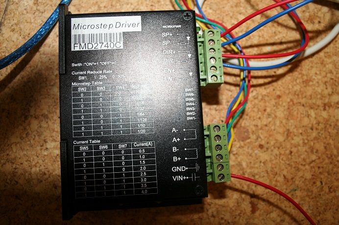
hi, the microstep driver is a FMD2740C . apart from adding a power supply to it is there any other wiring that needs to be put in place. also how do you find the pin numbers from the card. thanks
-
Ok they are 50V drives so you will need about 36 - 45 volt DC power supply. Originally Posted by terry1956
Also the dip switches you have them set at 0.5A which is far to low.. So set sw5 to on sw6 to off sw7 to on that will give you about 3 A
Are you using mach3 or what?
Edit I see it runs off usbcnc so I think this is the manual http://www.variometrum.com/PDF/USBCNC_csatolo_ENG.pdfLast edited by Clive S; 09-01-2017 at 06:03 PM. Reason: added text
..Clive
The more you know, The better you know, How little you know
-
09-01-2017 #4
Last Activity: 16-08-2023
Hi.on the motor driver there is a power in marked V+ which matches a terminal on the 36v power supply which came with the kit.however the second driver inlet is marked G for ground.the only G terminal on the power supply is on the inlet 240v side.the only free terminal is marked V-. So do I wire the driver G terminal to the G terminal on the power supply or to the free V- terminal. There are two leads on the driver,I take it the green one is power ok and the red one bad news.
-
09-01-2017 #5
 Last Activity: 24-07-2022


Post a picture of the power supply terminals.
Gerry
______________________________________________
UCCNC 2022 Screenset
Mach3 2010 Screenset
JointCAM - CAM for Woodworking Joints
-
09-01-2017 #6
Last Activity: 16-08-2023
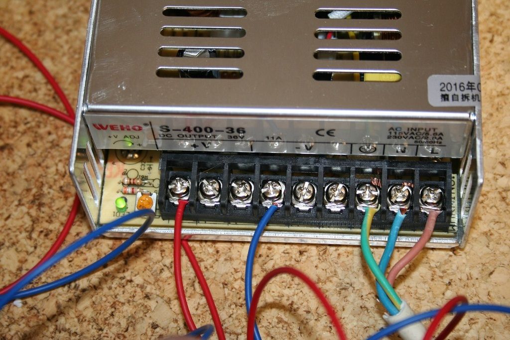
shows both units
-
the -ve with the blue wire connected on the power supply goes to the GND on the driver next to Vin+
..Clive
The more you know, The better you know, How little you know
-
09-01-2017 #8
Last Activity: 16-08-2023
hi clive, just did this and I had a green led showing on the driver and also the red one. I did not take things further. don't think that the red one is a good sign. so what to do next???
-
09-01-2017 #9

 Last Activity: 15-04-2024


-
Boyan the link is in post 9 Originally Posted by Boyan Silyavski
..Clive
The more you know, The better you know, How little you know


 Reply With Quote

Thread Information
Users Browsing this Thread
There are currently 1 users browsing this thread. (0 members and 1 guests)
Similar Threads
-
anyone using an e-cut 1 mhz usb breakout board
By nobby in forum Control Hardware & SystemsReplies: 10Last Post: 22-10-2018, 11:50 PM -
help needed with breakout board
By terry1956 in forum Motor Drivers & ControllersReplies: 22Last Post: 07-09-2016, 07:58 PM -
Breakout Board
By Tomnewry in forum General ElectronicsReplies: 2Last Post: 12-12-2013, 07:24 PM -
FOR SALE: PMDX-122 Breakout board
By IN-WondeR in forum Items For SaleReplies: 0Last Post: 14-12-2011, 04:05 PM -
Breakout Board
By croy in forum Electronic Project BuildingReplies: 10Last Post: 18-08-2011, 07:50 AM

Bookmarks