-
29-04-2017 #1
Hello all,
I've been meaning to make this for a while - it's a laughably simple project (for all but the electronics simpletons like myself).
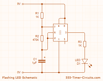
So, I'm going to base my circuit on this one:
http://www.555-timer-circuits.com/flashing-led.html

...except I'll be using a 12v PS and one of these instead of an LED:
R1 and R2 control the speed at which the LED flashes - or rather (I'm hoping) the solenoid will open and close - as it is, the led flashes rather quickly - I'm planning to replace these two resistors with a couple of linear pots so that I can adjust open/close times - any recommendations for pot values I should be looking at..?
Also, the cap value? As I'm using a 12v supply will I need to change the cap - what difference would a different value make to this circuit?
Finally, will this work..?! Have I correctly assumed that R1 and R2 are independently controlling open/close times?
Any advice appreciated..!
Wal.
-
29-04-2017 #2
Wal I have a 12V solenoid air valve if you want it give me a shout. I think you might need a fly back diode across it.
..Clive
The more you know, The better you know, How little you know
-
The Following User Says Thank You to Clive S For This Useful Post:
-
29-04-2017 #3
Cheers Clive,
I'll drop you an email. You might need to explain the fly back diode to me...
Wal.
-
29-04-2017 #4
I would expect the NE555 can not provide enough current to operate the
solenoid valve without the addition of a high gain power transistor
like the TIP122
the 1N4001 across the coil is the flyback suppressor diode
when the transistor is switched on the diode is reverse biased so it does not conduct
when the transistor switches off a large back emf is produced
the diode provides a path for the current to flow instead of
driving the transistors collector more positive than the positive supply
JohnLast edited by john swift; 29-04-2017 at 01:59 PM.
-
The Following User Says Thank You to john swift For This Useful Post:
-
29-04-2017 #5
Cheers John,
I spotted this online earlier:
http://www.robotshop.com/uk/adjustab...ering-kit.html
Might do the trick, although the output voltage is 24v as opposed to the 12v the solenoid wants.
Cheers for the additions to the diagram, I'll post my results if I make one..!
Wal.
-
29-04-2017 #6
-
The Following User Says Thank You to Clive S For This Useful Post:
-
29-04-2017 #7
Cheers Clive..!
That's me being dumb again...! If it helps anyone else reading this:
The output is the relay contacts RATED at 24V 3A and not outputting anything. ie the relay is just a switch that changes state. So the control circuit runs off 12V and you can run the air valve off 12v through the relay.
Thanks again Clive!
Wal.
-
29-04-2017 #8
-
01-05-2017 #9
-
02-05-2017 #10
Last edited by A_Camera; 02-05-2017 at 12:20 PM.
Thread Information
Users Browsing this Thread
There are currently 1 users browsing this thread. (0 members and 1 guests)
Similar Threads
-
NEW MEMBER: First timer
By bofred in forum New Member IntroductionsReplies: 4Last Post: 01-12-2014, 09:23 PM -
EMI Filters, any purpose in a diy control circuit?
By GTJim in forum General ElectronicsReplies: 6Last Post: 14-03-2014, 11:38 PM -
Custom Vacuum Table 'Hold Down' System - piping/valve advice
By FlightCaseCo in forum Machine DiscussionReplies: 4Last Post: 16-01-2012, 06:56 PM -
TB6560 > Timer > GMFC
By Theo in forum Motor Drivers & ControllersReplies: 0Last Post: 17-10-2010, 06:59 PM -
NEW MEMBER: Old timer, still learning, Virginia, USA
By GerryR in forum New Member IntroductionsReplies: 1Last Post: 13-10-2010, 10:41 PM


 Reply With Quote


Bookmarks