
-
11-08-2017 #1

 Last Activity: 3 Weeks Ago


Hi all, this is the first post of my build log.
After reading a lot on this site i made some of the build decisions.
Basically it is a half raised gantry router.
Planning on 15mm alu toolingplate Z-Axis
1st.. size.
- 1500x 800 x 200 mm work area.
2nd materials to be cut.
- Wood and aluminium.
3rd basic building material.
- Steel box section. 120×80×4mm and 80x80x4mm
Router type.
- 4 bearing Chinese WC ER20 2..2kw
VFD ...
-Danfoss FC-51 type.
linear stuff.
- 20mm rail, c7 rolled ballscrew1610 for Y, 1605 for Z, 2010 for X
- 4 x nema 23 3 or 4 NM type
Or maybe 2 nema23 and 1 nema 34...
Is undecided for now.
Tools
-I have no access to mill.
-I have access to old lathe. but no real experience
- Basic hand / power tools.
- Design sw
Solidworks.
Cnc controls
- Eyeballing uccnc300eth
- Digital drivers 68v diy psu
So that is the plan.
I do notice i am refining the plan on the go.
Verstuurd vanaf mijn SM-A320FL met TapatalkLast edited by driftspin; 11-12-2017 at 12:19 AM.
-
11-08-2017 #2
 Last Activity: 20-04-2020
Hello!
Sounds awsome :D
Good luck and for ours sake post a lot of pictures..!
Skickat från min SM-N910C via Tapatalk
-
11-08-2017 #3
Last Activity: 3 Weeks Ago
Yes... pictures... ill try to post on every progress..
 Originally Posted by Nr1madman

Actually i started work on a design over a year ago.
1st the plan was to make an adjustable bed.
This over complicated the design.... or weakened it...
now the design is more basic.
Verstuurd vanaf mijn SM-A320FL met TapatalkLast edited by driftspin; 11-08-2017 at 07:55 PM. Reason: Pictures added
-
11-08-2017 #4
Last Activity: 3 Weeks Ago
Buying steel is not a problem.
Getting 6mtr length box section cut or stored in my shed is..
Shed is just 5.7m X 3.7m
So i orderd the steel box section, and some end plates pre cut, ready to weld up.
A friend of mine works with steel, he is my main supplier for steel related stuff.
We share a hobby 150 Amp migwelder. (Cebora)
It was bought for automotive related welding.
-
11-08-2017 #5
Last Activity: 3 Weeks Ago
This is what the start of my cnc hobby looked like in the back of my car
I spirit levelled the top of a standard used desk for setting up the bed box section.
Dont ask me why i did not start with the legs of the frame.
Ok .... its gonna be bulky...
Tag welding it up
After final welding i found out warping will happen...
Total distortion is now +/- 1.5 mm
1850x1160 mm total size.
I have read on this forum this could happen... But is was still more than i expected.
Epoxy has to solve this problem in a later stage...
More to come.
Verstuurd vanaf mijn SM-A320FL met TapatalkLast edited by driftspin; 14-09-2017 at 07:11 PM.
-
11-08-2017 #6
 Last Activity: 3 Hours Ago


 I would re think this for me I would use 1610 for X & Y and 1605 for Zlinear stuff.
- 20mm rail, c7 rolled ballscrew1610 for Y,Z, 2010 for X
- 4 x nema 23 3 or 4 NM type
Or maybe 2 nema23 and 1 nema 34...
Is undecided for now.
With nema 23 3.1nM
Have a look a Joe's build http://www.mycncuk.com/threads/4513-...ight=joeharris..Clive
The more you know, The better you know, How little you know
-
11-08-2017 #7
Last Activity: 13-07-2023

looks nice, I'd just be a little concerned about how you are going to make the rails work on the gantry? That orientation is going to be very tricky to align within the required tolerances on a steel beam. What was your plan in that regard?
-
11-08-2017 #8
Last Activity: 3 Weeks Ago
Hi Clive, Originally Posted by Clive S
I was playing around with the stepper calculator from this forum...
1605 on Z 1:1 ? or also reducted?
Picking the 2010 over a 1610 on x axis ,1700mm between bearings, is about critical rpm vs speed... looks like i need 2010 to reach up to or over 5 m/min.
What is your opinion on these?
Since i am a beginner i am not sure what the max speed is i would need for cutting and rappids
Some other materials might need faster speeds i am not sure...
2.2kw spindle makes cutting at lower rpm easier combined with a quality vfd.
I am trying to pick the right quality parts to make a versatile machine.
Any help is welcome.
Please share your concerns.
No linear parts or elektronics are bought yet.
Verstuurd vanaf mijn SM-A320FL met Tapatalk
-
11-08-2017 #9
Last Activity: 3 Hours Ago
Yes I agree. Have you decided on one motor or two?Picking the 2010 over a 1610 on x axis ,1700mm between bearings, is about critical rpm vs speed... looks like i need 2010 to reach up to or over 5 m/min.
Don't buy any electrics until you have it all drawn up in CAD AM882 or EM806 work well for the drives at 68V..Clive
The more you know, The better you know, How little you know
-
The Following User Says Thank You to Clive S For This Useful Post:
-
12-08-2017 #10
Last Activity: 3 Weeks Ago
Dear Zeeflyboy, Originally Posted by Zeeflyboy
I hope for a miracle by epoxy
First one needs a zero reference for horizontal level.
I think it was Boyan who explained on the forum he made a reference level surface for this on a concrete floor by pouring epoxy.
I will try this way.
I will spirit level and anker bolt my frame to the concrete floor before pourings so nothing can move and use the x poured epoxy rail mounting surface for this.
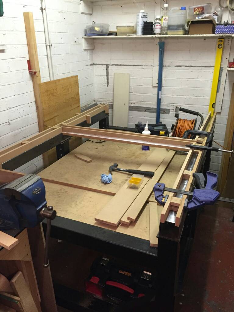
Pouring the rail mounting surface for X will be done like the example from a forum member see picture.
like the X axis the 4 mounting surfaces on the gantry will be epoxy levelled.
In 2 steps...
Step 1 I will do the 2 gantry X rail carriage mounting surfaces, and bottom Y rail mounting surface pouring, in 1 go. ( gantry upside down )
There will be an epoxy levelling bridge between the 2 carriage mounting surfaces
Similar to x rail pouring setup
So now those 3 surfaces will be in the same plain.
After curing..
Step 2 The gantry can now be flipped to normal position and top Y axis rail mounting surface can be poured..
Placing the gantry in the normal position on the mounting surface of the x rail should give the best possible reference for a level plain.
After pouring Y bottom and top should be in the same plain..
In theory this should work.
I know this will be a critical process.
When this method fails i will redesign and have the gantry (rail) mounting surfaces milled. nothing much changes only a few pounds of steel added.
When milling is needed i will upgrade the gantry box section to 80x120x8 or 10 to have some meat to mill
I do want to avoid **bolting** the gantry sides to the gantry Y-axis.
I prefer welded solid for best rigidity.
But welding solid must be avoided going that route, because of warping.
I have no friends with a mill capable of box section 1200X120x80.
Would a surface grinder work for this purpose?
Any other thoughts?
Verstuurd vanaf mijn SM-A320FL met Tapatalk

 Reply With Quote
Thread Information
Users Browsing this Thread
There are currently 1 users browsing this thread. (0 members and 1 guests)
Similar Threads
-
BUILD LOG: First time build - Steel Frame CNC Router
By examorph in forum DIY Router Build LogsReplies: 144Last Post: 19-10-2023, 06:25 PM -
BUILD LOG: First Build 5 x 12 Steel Frame CNC router
By Scott Damman in forum DIY Router Build LogsReplies: 104Last Post: 18-01-2017, 06:36 PM -
BUILD LOG: Steel frame cnc router design/build
By CraftyGeek in forum DIY Router Build LogsReplies: 110Last Post: 06-05-2015, 10:00 PM -
600x900 Steel welded router build
By embraced in forum Gantry/Router Machines & BuildingReplies: 7Last Post: 08-10-2014, 10:55 PM -
BUILD LOG: First steel diy CNC router build
By ivars211 in forum DIY Router Build LogsReplies: 59Last Post: 28-07-2014, 08:29 PM

Bookmarks