
Hybrid View


-
I would re think this for me I would use 1610 for X & Y and 1605 for Zlinear stuff.
- 20mm rail, c7 rolled ballscrew1610 for Y,Z, 2010 for X
- 4 x nema 23 3 or 4 NM type
Or maybe 2 nema23 and 1 nema 34...
Is undecided for now.
With nema 23 3.1nM
Have a look a Joe's build http://www.mycncuk.com/threads/4513-...ight=joeharris..Clive
The more you know, The better you know, How little you know
-
11-08-2017 #2

 Last Activity: 13-07-2023


looks nice, I'd just be a little concerned about how you are going to make the rails work on the gantry? That orientation is going to be very tricky to align within the required tolerances on a steel beam. What was your plan in that regard?
-
12-08-2017 #3
 Last Activity: 13-06-2024
 Dear Zeeflyboy,
 Originally Posted by Zeeflyboy

I hope for a miracle by epoxy
First one needs a zero reference for horizontal level.
I think it was Boyan who explained on the forum he made a reference level surface for this on a concrete floor by pouring epoxy.
I will try this way.
I will spirit level and anker bolt my frame to the concrete floor before pourings so nothing can move and use the x poured epoxy rail mounting surface for this.
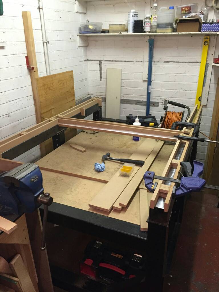
Pouring the rail mounting surface for X will be done like the example from a forum member see picture.
like the X axis the 4 mounting surfaces on the gantry will be epoxy levelled.
In 2 steps...
Step 1 I will do the 2 gantry X rail carriage mounting surfaces, and bottom Y rail mounting surface pouring, in 1 go. ( gantry upside down )
There will be an epoxy levelling bridge between the 2 carriage mounting surfaces
Similar to x rail pouring setup
So now those 3 surfaces will be in the same plain.
After curing..
Step 2 The gantry can now be flipped to normal position and top Y axis rail mounting surface can be poured..
Placing the gantry in the normal position on the mounting surface of the x rail should give the best possible reference for a level plain.
After pouring Y bottom and top should be in the same plain..
In theory this should work.
I know this will be a critical process.
When this method fails i will redesign and have the gantry (rail) mounting surfaces milled. nothing much changes only a few pounds of steel added.
When milling is needed i will upgrade the gantry box section to 80x120x8 or 10 to have some meat to mill
I do want to avoid **bolting** the gantry sides to the gantry Y-axis.
I prefer welded solid for best rigidity.
But welding solid must be avoided going that route, because of warping.
I have no friends with a mill capable of box section 1200X120x80.
Would a surface grinder work for this purpose?
Any other thoughts?
Verstuurd vanaf mijn SM-A320FL met Tapatalk
-
12-08-2017 #4

 Last Activity: 15-04-2024


Thats how i did it on the gantry, my first build. gantry was flipped 180 degree and i poured gantry sides and lower beam epoxy. Then flipped and did upper rail. No problem.
But you will need a straight edge and 2 precision squares for later when mounting the rails and so...
-
14-08-2017 #5
Last Activity: 13-07-2023
Sounds good! Will watch with interest. Good luck! Originally Posted by driftspin
Last edited by Zeeflyboy; 14-08-2017 at 12:33 PM.
-
11-08-2017 #6
Last Activity: 13-06-2024
Hi Clive, Originally Posted by Clive S
I was playing around with the stepper calculator from this forum...
1605 on Z 1:1 ? or also reducted?
Picking the 2010 over a 1610 on x axis ,1700mm between bearings, is about critical rpm vs speed... looks like i need 2010 to reach up to or over 5 m/min.
What is your opinion on these?
Since i am a beginner i am not sure what the max speed is i would need for cutting and rappids
Some other materials might need faster speeds i am not sure...
2.2kw spindle makes cutting at lower rpm easier combined with a quality vfd.
I am trying to pick the right quality parts to make a versatile machine.
Any help is welcome.
Please share your concerns.
No linear parts or elektronics are bought yet.
Verstuurd vanaf mijn SM-A320FL met Tapatalk
-
Yes I agree. Have you decided on one motor or two?Picking the 2010 over a 1610 on x axis ,1700mm between bearings, is about critical rpm vs speed... looks like i need 2010 to reach up to or over 5 m/min.
Don't buy any electrics until you have it all drawn up in CAD AM882 or EM806 work well for the drives at 68V..Clive
The more you know, The better you know, How little you know
-
The Following User Says Thank You to Clive S For This Useful Post:
-
12-08-2017 #8
Last Activity: 13-06-2024
Dear Clive S, Originally Posted by Clive S
My design dictates at least 2 idler pullys per ballscrew if i want to go single x axis nema 34 stepper... and have the whole bed space.
Or... i have to limit bed space and cross the bed...There is room in the design to do this though.
And 1 side is up against a wall anyways.
When going single stepper,
i think i would buy a wide stepper pully,
and shift the ballscrews a belt width and use 2 belts, 1 for every ballscrew.
For now a 2 stepper x setup looks more convenient from a mechanical point of view.
2 short belts.
lots of bed space
My Electronic pov is opposit.
For inertia it seems, in my mind, better too.
2 powerful 3+Nm steppers on high voltage digital drivers. Instead of a single bigger 8/12nm nema34. this is just a gut feeling , not based on any sound research.
Not sure what makes a 3, 3,1 or 4 Nm nema 23 stepper best choice.
Just high amps low inductance right?
Any thoughts?
Verstuurd vanaf mijn SM-A320FL met Tapatalk
-
That's what I use you can run them 1.5:1 or 2:1 I used 3.1Nm but with 1610 screws motors from https://www.cnc4you.co.uk/Stepper-Mo...YGH301B-Nema23For now a 2 stepper x setup looks more convenient from a mechanical point of view.
2 short belts.
lots of bed space
with am882 drives from China
I do have a nema 23 4Nm on my mill but don't see a difference in them..Clive
The more you know, The better you know, How little you know
-
13-08-2017 #10
Last Activity: 15-04-2024


 Reply With Quote
Thread Information
Users Browsing this Thread
There are currently 8 users browsing this thread. (0 members and 8 guests)
Similar Threads
-
BUILD LOG: First time build - Steel Frame CNC Router
By examorph in forum DIY Router Build LogsReplies: 144Last Post: 19-10-2023, 06:25 PM -
BUILD LOG: First Build 5 x 12 Steel Frame CNC router
By Scott Damman in forum DIY Router Build LogsReplies: 104Last Post: 18-01-2017, 06:36 PM -
BUILD LOG: Steel frame cnc router design/build
By CraftyGeek in forum DIY Router Build LogsReplies: 110Last Post: 06-05-2015, 10:00 PM -
600x900 Steel welded router build
By embraced in forum Gantry/Router Machines & BuildingReplies: 7Last Post: 08-10-2014, 10:55 PM -
BUILD LOG: First steel diy CNC router build
By ivars211 in forum DIY Router Build LogsReplies: 59Last Post: 28-07-2014, 08:29 PM

Bookmarks