
-
12-09-2018 #11

 Last Activity: 2 Weeks Ago


 Hi Neely Boy,
 Originally Posted by Nealieboyee

What is your free Z height ?
Looks like there will be very little room left for clamping solution spoilerboard and length of the cutter...
Maybe you could lower the bed in your design a little to free up some space.
What material thickness are you looking to cut?
Beltreduction has some advantages.
-Foot print
-Option to change steps per mm later on.
-Noise reduction.
-Less stepper vibration transfer to cutter.
Also you can gain speed vs ballscrew rpm
when you raise the pitch of the ballscrew
and "belt pulley reduce" the ballscrew rpm vs stepper without losing resolution.
This is usefull when you hit the critical rpm for a given ballscrew/pitch vs speed.
Also some high pitch screws tend to be more efficient.
But since you already ordered this is a non issue..
Did you order ballscrews prepped for pulleys? I ordered mine with a slightly longer F lenght shaft... 30mm of pulley shaft.
Hope this helps.
Did i forget anything?
Grtz Bert
Verstuurd vanaf mijn SM-A320FL met TapatalkLast edited by driftspin; 12-09-2018 at 06:26 PM.
-
12-09-2018 #12
 Last Activity: 01-12-2023
Originally Posted by driftspin
Last Activity: 01-12-2023
Originally Posted by driftspin
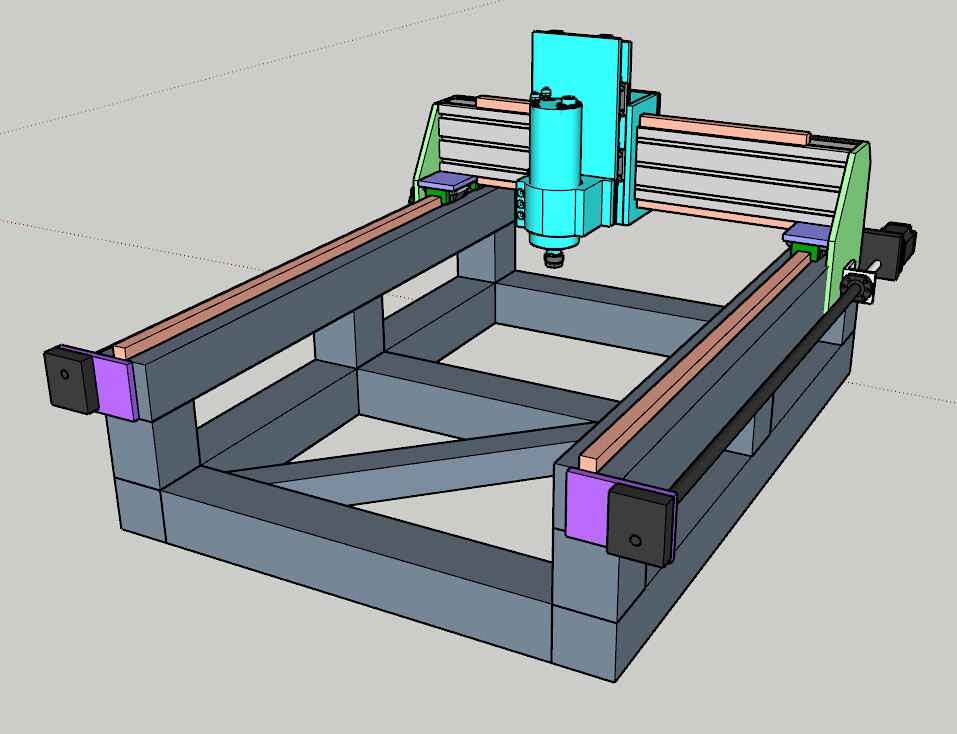
Whoops....I just placed a sketchup model of the 2.2kw spindle into my model and the tip of the collet was touching box section. I'll need to add....how much below that? 100mm, 150mm?
With that z height, 0mm lol. I'm hoping go from 0 up to 30-40mm.What material thickness are you looking to cut?
Nope. I ordered plain finished ballscrews which couple directly to the steppers.Beltreduction has some advantages.
-Foot print
-Option to change steps per mm later on.
-Noise reduction.
-Less stepper vibration transfer to cutter.
Also you can gain speed vs ballscrew rpm
when you raise the pitch of the ballscrew
and "belt pulley reduce" the ballscrew rpm vs stepper without losing resolution.
This is usefull when you hit the critical rpm for a given ballscrew/pitch vs speed.
Also some high pitch screws tend to be more efficient.
But since you already ordered this is a non issue..
Did you order ballscrews prepped for pulleys? I ordered mine with a slightly longer F lenght shaft... 30mm of pulley shaft.
Would 3.1Nm steppers be enough here or should I go to 4Nm? Just realised I only ordered three ball screws, and I'll need a second one for the Y axis...I'll have to get one locally or add it to my order for the spindle and electronics from Fred.
Does it look rigid enough with 50x50mm square tube?Did i forget anything?
Thanks very much for taking the time to answer my questions. Much appreciated.
-
13-09-2018 #13
Last Activity: 2 Weeks Ago
Well 50x50 does not sound like a lot.
webbed in the bed it could be enough.
If you decide to go 50x50 at least make sure it is 4 or better 5mm wall thickness, much easier with tapping threads.
For the size i would go 80x80x4
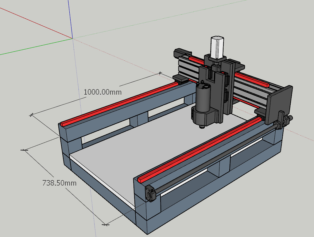
The main thing is your total footprint.
It is 1000x700 right?
When you can run FEA on your design you know.
I did some basic checks on my design.
Quickly went for 80x80x4 bed and 80x120x4 gantry parts.
Get end caps on the box section.
I think you need to make the gantry as rigid as reasonably possible.
You can easily make the gantry 80x120...
Massive impact on rigidity.
Only 3 cm extra in the design.
Grtz Bert.
Verstuurd vanaf mijn SM-A320FL met TapatalkLast edited by driftspin; 13-09-2018 at 07:16 PM.
-
13-09-2018 #14
Last Activity: 01-12-2023
I went with the 50x50mm because it was free for 7.5m length :). If I go to 80x80mm, I will have to shrink the height due to the cost. The new 80x80mm design would look like the one attached. What do you think? I've also increased the free space between cutting bed and spindle to 130mm. My gantry is already 120x80mm. Originally Posted by driftspin
-
14-09-2018 #15
Last Activity: 2 Weeks Ago
Well free is the magic word :-) Originally Posted by Nealieboyee
Just make sure ther is enough meat to tap threads in for the linear rail bolts.
Also you need at least 4cm of width flatsurface to pour epoxy on the steel.
Make sure you have that.
Grtz Bert
Verstuurd vanaf mijn SM-A320FL met Tapatalk
-
14-09-2018 #16
Last Activity: 2 Weeks Ago
Btw, Originally Posted by driftspin
Why are the the z carriages up that high?
And close to gether?
Move those to the top and lower horizontal plates.
So top Z and Y and bottom Z and Y carriage are really close to gether, assuming X is the bed.
Grtz Bert.
Verstuurd vanaf mijn SM-A320FL met Tapatalk
-
22-09-2018 #17
Last Activity: 01-12-2023
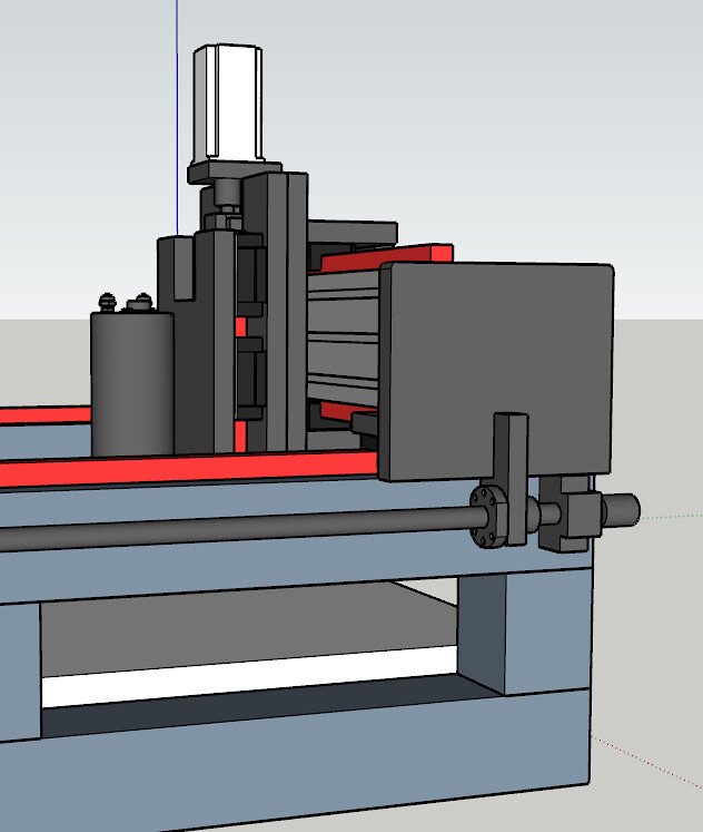
Thanks for your comments. Originally Posted by driftspin
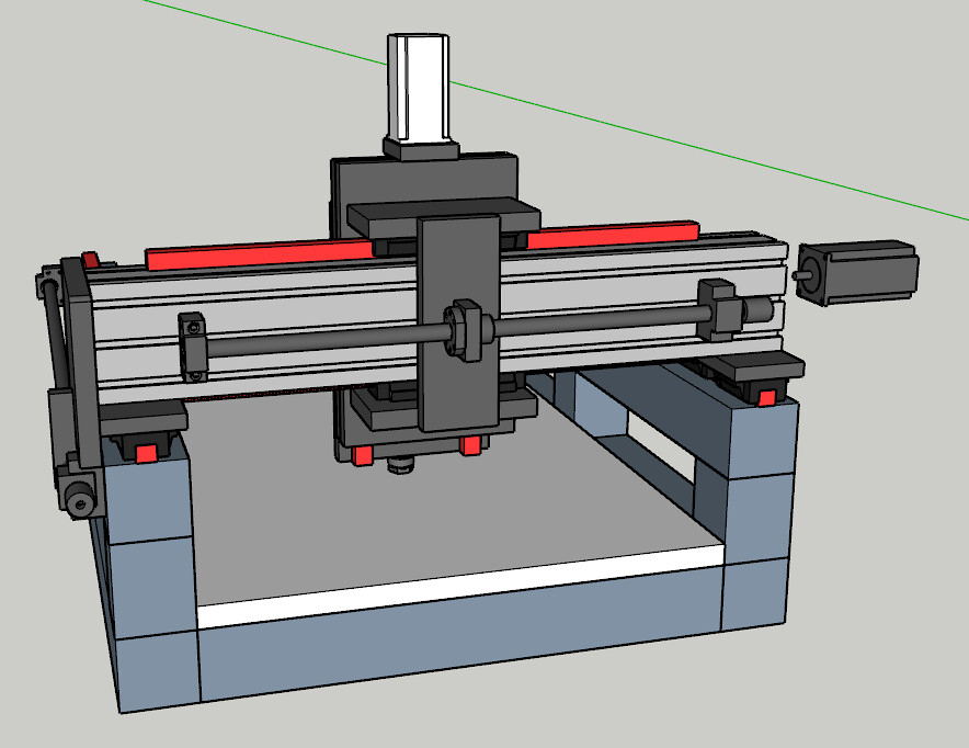
I did that because the further I move them apart, the less z height I have, because I have only 300mm rails for the Z axis.
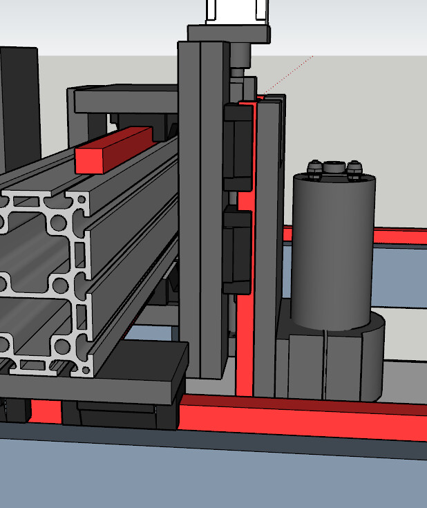
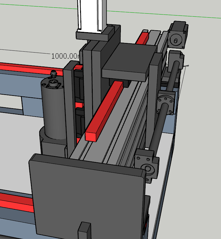
Here is the machine at the moment. The z axis is at the lowest point of its travel. I've modelled the ballscrews and rails etc exactly as they are. They arrived a few days ago. Still waiting for the second ballscrew for the x axis.
My only problem was trying to keep the z axis as close to the Y as possible, so that there is less overhang or twist forward on the gantry. So I had to move the ballscrew to the back of the gantry. Not ideal, but with everything being 16mm and 20mm alu plate, I figured it wouldn't pose too much of a problem. Thoughts?
I have now sourced 80x80x5mm steel box section, and I got it through a friend at work for £76 for a 7.5m length. Not too bad!
I've also ordered a 2.2kw water cooled spindle, 425oz motors and drivers. I'll be buying the transformers and caps soon for the power supply. Any idea what control board I should use?
Note I haven't modelled the second ballscrew for the x axis. Its basically a copy of the right hand side one.
Please let me know your thoughts?
Cheers
Neal
-
22-09-2018 #18
Last Activity: 2 Weeks Ago
For controls... well it all depends.
I have UCCNC / 300eth icw two cheap 5 axis boards. trying to delay buying UB1.
Will you be running 3 or 4 steppers?
A single 5 axis board icw 4 steppers and auto homing 4 axis X-A Y and Z only leaves you with 1 estop input left and no Zero probe input.
So plan ahead.
You will also need outputs for
spindle
spindle cooling
air blast
fluid spray
Vacuum
I think UCCNC does everything you need.
Check out what controller fits your needs.
the 100, 400, 300.
I have no experience with something else so please ask around for opinions.
Grtz Bert.
Verstuurd vanaf mijn SM-A320FL met Tapatalk

 Reply With Quote
Thread Information
Users Browsing this Thread
There are currently 1 users browsing this thread. (0 members and 1 guests)
Similar Threads
-
Aluminium Extrusion Router Build
By NFryer in forum Gantry/Router Machines & BuildingReplies: 76Last Post: 03-07-2019, 07:59 PM -
Homemade CNC with Scrap + Chinese parts || Objective: Milling Aluminium ||
By laranjas3 in forum Gantry/Router Machines & BuildingReplies: 7Last Post: 16-11-2017, 10:18 PM -
FOR SALE: Aluminium Extrusion
By vigen20 in forum Items For SaleReplies: 2Last Post: 24-07-2012, 11:01 PM -
BUILD LOG: Aluminium Extrusion CNC Router Build
By joshendy in forum DIY Router Build LogsReplies: 9Last Post: 10-04-2012, 08:26 PM -
BUILD LOG: Work scrap bin router build
By Vic66 in forum DIY Router Build LogsReplies: 32Last Post: 17-01-2010, 08:51 PM

Bookmarks