
Thread: Rotating Ballnut - design ideas
Threaded View


-
27-11-2016 #11

 Last Activity: 12-01-2017

 Thanks for your input.
 Originally Posted by Boyan Silyavski

I didn't realize the bearing and ballnut/screw got significantly hot during machining. I suspect that this will be less of a concern for me as the type of machining I will do will not include much in the line of high-speed toolpaths and rapid moves in general will be at a minimum. I suspect the concern with heat here is in regard to maintaining cutting tolerances and repeatability, as the bearing and screw materials will handle the heat satisfactorily. Is this your understanding as well?
Of course minimizing the contact area and pressure between bearing and race will similarly minimize the generation of heat, which is where the angular contact bearings excel. There's not a whole lot you can do about the ballnut and the ballscrew interaction though.
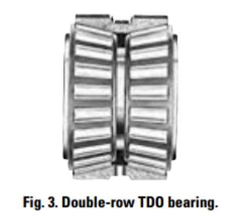
These are 2788 bearings with 2720 cup. I just had a quick look at Timken's tapered roller bearing engineer's guide and didn't see any indication that the effective bearing spread (distance between bearings) was critical. In fact, I didn't even see where they made any spread recommendations for this type of bearing at all. Interestingly, I just saw that they make a Double Row Tapered Roller Bearing unit that is completely self-contained with a spread much closer than my own design: Originally Posted by Boyan Silyavski
C90 - Dynamic Radial Rating (90 million revolutions): 5060 lbf / 22500 N Originally Posted by Boyan Silyavski
C1 - Dynamic Radial Rating (1 million revolutions): 19500 lbf / 86900 N
C0 - Static Radial Rating: 23000 lbf / 102000 N
Ca90 - Dynamic Thrust Rating (90 million revolutions): 2630 lbf / 11700 N
Not sure about RPM, but surely my servo motor at 1:1 or 2:1 pulley ratio will never be able to exceed the limitations of these bearings, I suspect.
My goal is to keep the overall length of the unit as short as possible. Every millimeter of assembly length is a millimeter LESS travel I get out of this axis. The problem I was running into when designing the bearing case as a single piece with the pulley in the middle of the bearings (like the ones you and Jonathan are using), is that the slot to insert the pulley has to be very wide so I'll have enough room to insert the key into the keyway in the shaft, then drop the pulley in and slide it over the key. This makes the whole unit prohibitively long for my application. Originally Posted by Boyan Silyavski
I don't believe belt tension will throw the axial alignment off as the pulley is positioned directly against the bearing, minimizing the lever-arm.
Presuming I do the machining carefully and from one side, the axial alignment of the bearings themselves should be just about perfect as the housing is a single piece of aluminum. The servomotor-pulley-to-ballnut-pulley alignment shouldn't be too difficult to handle with a separate, divorced mount, I wouldn't think.
I think the biggest downside to this is the cost of the bearings themselves. I tell myself that these bearings would be a once-in-a-lifetime investment for this machine. It would really stink if this design didn't do the job and I was left with 4 expensive, slightly-used bearings sitting on the shelf for the next 20 years.Last edited by SafeAirOne; 27-11-2016 at 12:15 PM.

 Reply With Quote
Thread Information
Users Browsing this Thread
There are currently 4 users browsing this thread. (0 members and 4 guests)
Similar Threads
-
Rotating Ball nut
By drumsticksplinter in forum Lead Screws, Nuts & SupportsReplies: 30Last Post: 12-05-2020, 08:01 PM -
Interesting Papers on heavy duty design, vibrations, composites and column design
By D.C. in forum Gantry/Router Machines & BuildingReplies: 15Last Post: 25-06-2016, 10:13 PM -
Rotating Ballnut Design MK3
By Jonathan in forum Linear & Rotary AssembliesReplies: 0Last Post: 15-12-2013, 01:35 PM -
advice on floating bearing - outer ting rotating
By dsc in forum Lead Screws, Nuts & SupportsReplies: 8Last Post: 18-11-2013, 02:23 PM -
Design help etc required with DIY CNC Router Design / Build
By MikeyC38 in forum Gantry/Router Machines & BuildingReplies: 12Last Post: 21-10-2011, 04:50 PM

Bookmarks