
Thread: Rotating Ballnut - design ideas
-
16-12-2013 #91

 Last Activity: 15-04-2024


 Actually if Jonathan or sb from the forum doesn't have the time to make the parts for me, i have to go to my local guy, who is way off with the 0.01mm, he works in the 0.5 zone definition
 Originally Posted by EddyCurrent


So i would update the drawings with extra drawing , made from OD100 and OD80 round bar. That way it would be more easy for him not to make a mistake an find the center. Further benefit will be that it could be mounted in cut in 2 pieces 85mm or 100mm spindle mount/not perfect but will work/ . anyway, i will mount it directly on its face, not using the bottom holes.
-
16-12-2013 #92

 Last Activity: 10-12-2021
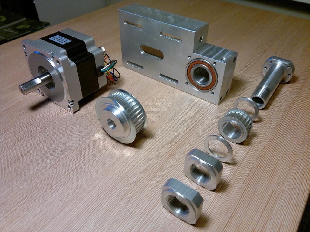
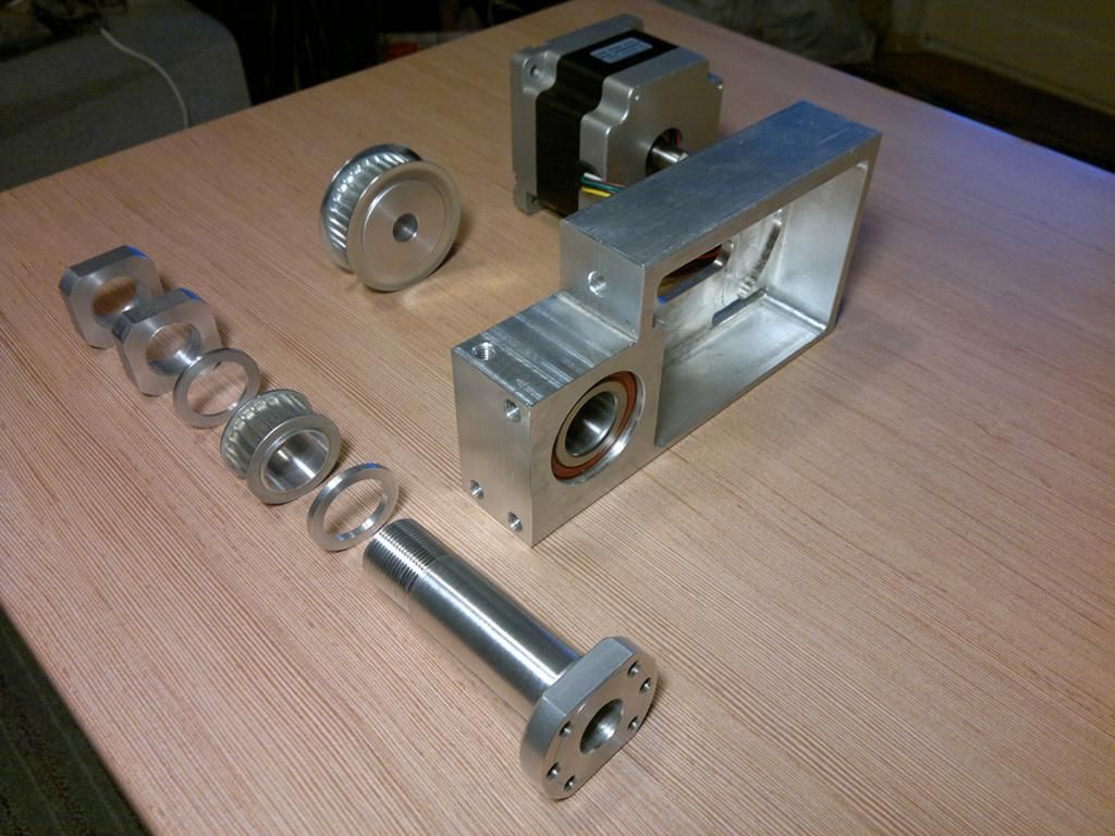
One grubscrew is enough for clamping the pulley to the motor shaft or should I use two at 90 degrees? Are there other simple methods that I could use to be able to change the pulley (ratio) more easily?
Here are my machined parts, still not assembled and tested:
-
16-12-2013 #93

 Last Activity: 17-05-2026
Machining looks very nice. G.
-
17-12-2013 #94
Last Activity: 15-04-2024
For the sake of experiment, found some providers of Servo motors with hollow shaft where a ball nut can be mounted. Usually the 3nm motors accept only16xx sizes, for 25xx sizes a 9Nm servos are offered.
I wanted to make sure Hybrid Closed Loop Stepper driver + motor+shipping + this assembly will not equal a proper servomotor price.
No prices on the sites/ means "in the thousands" to me/ . Well , one called me , wow, i got even more suspicious about the price. Now received the quote.
Wow, again. 1600eur the motor and the driver and cables. driver costs 420, so rest is the motor.
-
18-12-2013 #95
Last Activity: 15-04-2024
Guys, now the most stupid question: How to order the ball screws machined at both ends? Simple thread, long enough for 3 nuts? One inside, then mount plate then another plus locking one?
Last edited by Boyan Silyavski; 18-12-2013 at 04:11 PM.
-
18-12-2013 #96
 Last Activity: 05-04-2020

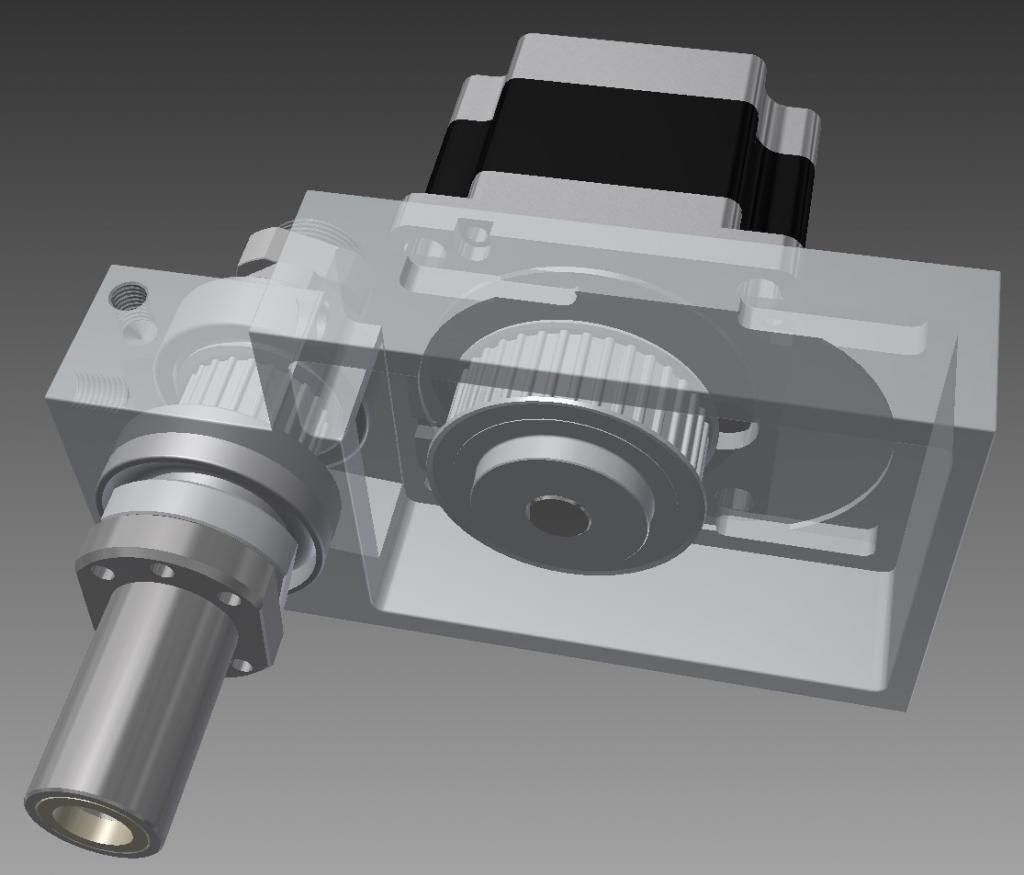
Paulus - I like the way you've designed it such that the housing is one part, however I'm slightly concerned by the apparent small spacing of the angular contact bearings. According to NSK, you need to have the angular contact bearings spaced by 1.5 times their external diameter, but it looks like in your design they're almost touching, or a double row bearing which wont qualify? I expect you'll still get a reasonably high critical speed from this setup, but not as high as it could have been. The reason the bearings need to be so rigid is that the ballnut will inevitably not be perfectly concentric to the screw. Ideally the error will be small, but any error will cause energy to be transferred from the ballnut to the screw causing them both to oscillate. Both the nut and screw need to be rigidly held to suppress this.
Originally Posted by silyavski
Make your own.
I got mine machined the same as the standard end machining for the angular contact bearings at both ends, in case the rotating nut didn't work. All you really need is a cylindrical portion and a thread on both ends. On one end simply use the thread to clamp the screw, ideally into a hole the same diameter as the cylindrical portion so it's held rigidly. Something similar on the other end, except you can use the thread to tension the screw a bit if your frame is strong enough. Also, design the end mounts in two parts so you can adjust the ends of the screw to be concentric with the bearings. Originally Posted by silyavski
If you look earlier in the thread you'll see the end mounts I made are very simple - essentially just a block with a clearance hole. They work, but having a hole the same diameter as the screw instead of using it for adjustment will be better.
Edit: Idea for silvaski - to make the housing easier to machine, instead of boring the bearings from both sides you could bore from one side almost all the way through, then machine a spacer tube the right thickness to go in between the outer rings of the bearings.Last edited by Jonathan; 18-12-2013 at 04:31 PM.
-
18-12-2013 #97
Last Activity: 15-04-2024
I knew this is important. I was sleepy the other night when i made the Sketchup drawing and wondered why you separated them so much, but overlooked it. I even gave ideas how to be made shorter Originally Posted by Jonathan

-
21-12-2013 #98
Last Activity: 10-12-2021
Thanks Jonathan for your comments, Originally Posted by Jonathan
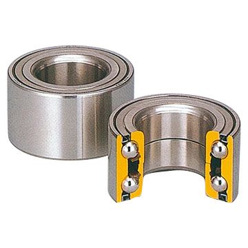
I needed a simple design as I don't have access to precision machining. I wanted one part housing without the need of bearing pair alignment. So I chose a double row? -or how it's called- bearing. Will see how it will perform.
Your last design is great, I will be able to modify mine if necessary :)
-
15-01-2014 #99
Last Activity: 10-12-2021
Jonathan, from your experience with rotating ballnut, what is the best way of lubrication? As continuous flow lubrication is excluded is it better to use grease instead of oil to last longer? What type of grease/oil do you recommend?
thanks
-
10-03-2014 #100
 cnctom
Last Activity:
Originally Posted by Jonathan
cnctom
Last Activity:
Originally Posted by Jonathan
Very nice design what size pulleys did you use i'm looking into building this myself but want to be sure to order the right pulleys and belt thanks for your time and engineering.

 Reply With Quote
Thread Information
Users Browsing this Thread
There are currently 2 users browsing this thread. (0 members and 2 guests)
Similar Threads
-
Rotating Ball nut
By drumsticksplinter in forum Lead Screws, Nuts & SupportsReplies: 30Last Post: 12-05-2020, 08:01 PM -
Interesting Papers on heavy duty design, vibrations, composites and column design
By D.C. in forum Gantry/Router Machines & BuildingReplies: 15Last Post: 25-06-2016, 10:13 PM -
Rotating Ballnut Design MK3
By Jonathan in forum Linear & Rotary AssembliesReplies: 0Last Post: 15-12-2013, 01:35 PM -
advice on floating bearing - outer ting rotating
By dsc in forum Lead Screws, Nuts & SupportsReplies: 8Last Post: 18-11-2013, 02:23 PM -
Design help etc required with DIY CNC Router Design / Build
By MikeyC38 in forum Gantry/Router Machines & BuildingReplies: 12Last Post: 21-10-2011, 04:50 PM

Bookmarks