
Thread: Rotating Ballnut - design ideas
Hybrid View


-
25-09-2016 #1

 Last Activity: 05-04-2020


 Is that just the pulleys you're after, or bearings and pulleys? For the bearings, I got the last lot from here:
 Originally Posted by mutzy

https://www.aliexpress.com/store/pro...053270817.html
[It may help to order 2 at a time to avoid customs charges. Not sure how it works in the USA, but I ordered two with no charges, then got taxed a lot when I bought 10 :(]
Regarding the pulleys, I can get 30t 5m HTD for about £6.30 each. Boring them accurately then drilling/tapping the setscrew holes takes maybe half an hour, so I'd be happy to sell them for £10 each plus postage.
This weekend, I made some progress on the six mounts I'm making:
I'm away racing next weekend, but after that I should have time to finish these ... at last.Last edited by Jonathan; 25-09-2016 at 10:09 PM.
-
12-10-2016 #2

 Last Activity: 26-10-2016
Impressive nuts! I just took a look at your e-moto webpage quickly too , wicked. Great project and racing at Isle of Man wow respect that place is nuts.
Hey I have a large router that is running well but I want to upgrade the main screw to a fixed screw rotating nut design. The screw is 40mm dia 10mm pitch and 3m long so its heavy. Running a 940W AC servo and a Grantite Devices VSD-XE servo drive, and 80VDC supply, I'm getting good response now with 8m/min velocity and about 400mm/s/s acceleration. This took a long time for me to work out the servo tuning but I got there in the end. I'd like to remove the rotating mass to improve my accelerations. The gantry it moves weighs around 150KG I estimate.
So I am wondering are you interested in building me a ball nut for this? Happy to pay market rates of course and if it helps fund any of your emoto projects then all the better. Please contact me if this is interest to you.
Below is my final servo response I got recently which I am really stoked about it, but to speed up my jobs I really want to up the accelerations.
cheers
Richard
Originally Posted by Jonathan
-
23-10-2016 #3
Last Activity: 05-04-2020
You can certainly say that of the riders! Originally Posted by richienz
With that size ballscrew then you do have a problem with the rotating inertia, not so much the 150kg gantry. Can you measure the ballnut - approximate it as cylinders, then we can work out the inertia of the ballnut compared to the ballscrew to see what you could gain by rotating the nut. Originally Posted by richienz
My PhD studies are taking up a lot of time at the moment (need to catch up after all the racing!), but I do intend to have time to finish some rotating nut assemblies soon. Originally Posted by richienz
What else can you plot from your system - can you plot the motor torque in addition to the speed response? If so, that's another way to work out the inertia and get better insight into how the system will behave. Originally Posted by richienz
-
25-10-2016 #4
Last Activity: 26-10-2016
I am too scared to watch the racing almost, its impressive riding nothing else is close really is it, but scary when a rider is badly hurt or killed, seems to be all too common. Originally Posted by Jonathan
I'll measure up the ball nut and screw and also try find the original part numbers and specs weights etc.
The PID loop tuning I struggle with, yes I can measure the currents I think , my Granite Devices VSD-XE servo drives have an inbuilt virtual oscilloscope that I use to measure the response with, to be honest the PID tuning I am very hit and miss with I can;t quite qork out what low pass filters I should use and why.......
I retuned the PID loops on both x and y on the weekend and its better but still I am sure there is room for significant improvement. whip of the screw is a problem too when I get over 600RPM approx. Thats a 10mm pitch per revolution screw (isthatthe correct terminology?) so thats a speed 6000mm/min , any faster and sometimes it whips and that really gives me the shits. I'm finding that small circle cuts say a 6mm end mill cutting a small 10mm dia helix has some error in the hole and I have to crank the speed back to around 1500mm/min for cutting (the timber) rather than running at higher speeds that I'd like to.
Anyway if you have time I would appreciate your guidance, keep on top of your studies thats top priority! Even if I can plagiarise your design and try build locally with some of your engineering input that would be greatly appreciated but if I can commission you to build one at the right price that works for us both then that's even better!!!
Funny I was a bit ambitious the last figures I quoted in my earlier post looked good on the scope but in real life cutting it was terrible!
Cheers
RichLast edited by richienz; 25-10-2016 at 02:38 AM.
-
05-11-2016 #5

 Last Activity: 15-04-2024

This cheap tool looks good for the KM03 locknut used if you have 20xx screws and using KM03 locknuts both sides
Still looking for an inexpensive tool for the KM04 nuts / 25xx screw and KM05/30xx screws. If sb knows , just post it here. Otherwise most probably you have to make yourself one so you could tighten and adjust tension of your ball screws
table of locknuts for reference below, i use 2 each side so total of 4 per screw , locktite on thread, red paint to mark any movement, did not know at the time about washers:
Last edited by Boyan Silyavski; 05-11-2016 at 11:06 PM.
-
26-11-2016 #6
 Last Activity: 12-01-2017

First post on this bulletin board; I enjoyed this thread...or at least what I had a chance to read using the spotty WiFi signal at work anyhow.
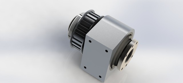
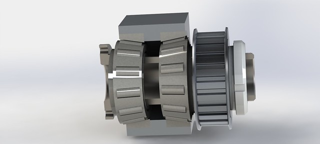
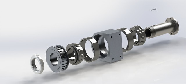
I find myself in need of a couple of rotating ballnuts for a 3000mm-long 2505 ballscrew, and have come across this older thread on the subject. I was inspired by the designs depicted here, and worked to duplicate/improve upon them when I became curious as to why angular-contact ball bearings were used instead of tapered roller bearings.
I'm trying to keep the unit as compact as possible and I suspect that the tapered roller bearings will help in that respect. The force on the hollow rotating shaft will be primarily axial, along the ballscrew axis with barely any radial load being applied by the tension of the timing belt/pulley.
I came up with the following design (sorry for the seemingly random view angles)--Any comments/input regarding it's viability?:
Thanks,
--MarkLast edited by SafeAirOne; 26-11-2016 at 09:32 PM. Reason: Typo/spelling
-
26-11-2016 #7
Last Activity: 15-04-2024
The bearings that we use here are angular contact ball bearings versus the roller bearings you have drawn in picture. Hiwin and other manufacturers use also ball bearings in their design. I dont know if you are aware of the fact, but for example my bearings and ball screw heat up quite seriously especially when i am doing some crazy fast trochoidal tool paths on wood. In the 20m/min region and good acceleration. Moving 200kg gantry obviously helps that.
The angular contact bearings must be separated at least 1x OD between, having in mind they are 45? degree i think. Obviously roller bearings could be much stronger in all directions load.
Whats the rating of that bearing? RPM?
I am asking my self, what are you trying to gain here? Why would you be braking the assembly to pieces? The motor alignment and ability to tighten correctly the belt while keeping that alignment is a crucial part of the design . Have that in mind. Any small imprecision on a 3 meter scale becomes big imprecision
-
25-04-2020 #8
 Last Activity: 25-04-2020
 Do you have design drawings to share for this? Originally Posted by SafeAirOne

 Reply With Quote
Thread Information
Users Browsing this Thread
There are currently 1 users browsing this thread. (0 members and 1 guests)
Similar Threads
-
Rotating Ball nut
By drumsticksplinter in forum Lead Screws, Nuts & SupportsReplies: 30Last Post: 12-05-2020, 08:01 PM -
Interesting Papers on heavy duty design, vibrations, composites and column design
By D.C. in forum Gantry/Router Machines & BuildingReplies: 15Last Post: 25-06-2016, 10:13 PM -
Rotating Ballnut Design MK3
By Jonathan in forum Linear & Rotary AssembliesReplies: 0Last Post: 15-12-2013, 01:35 PM -
advice on floating bearing - outer ting rotating
By dsc in forum Lead Screws, Nuts & SupportsReplies: 8Last Post: 18-11-2013, 02:23 PM -
Design help etc required with DIY CNC Router Design / Build
By MikeyC38 in forum Gantry/Router Machines & BuildingReplies: 12Last Post: 21-10-2011, 04:50 PM

Bookmarks