
Thread: Siff' Build Log
Threaded View


-
18-07-2011 #1

 Last Activity: 09-02-2012


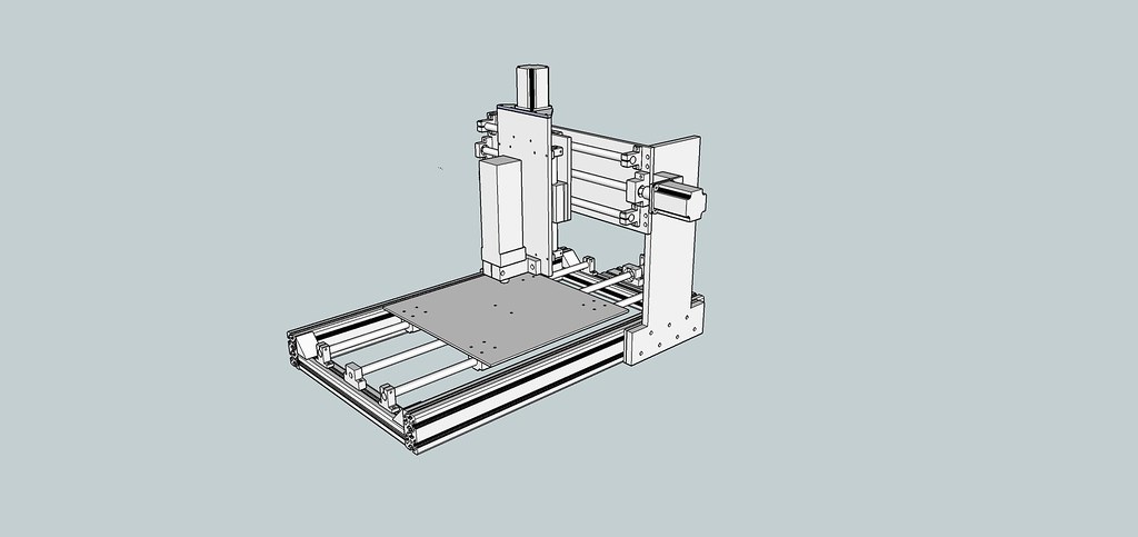
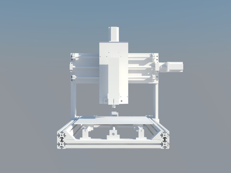
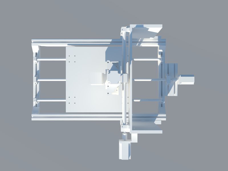
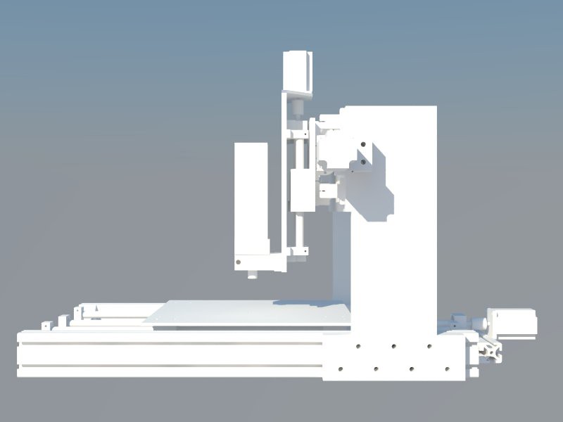
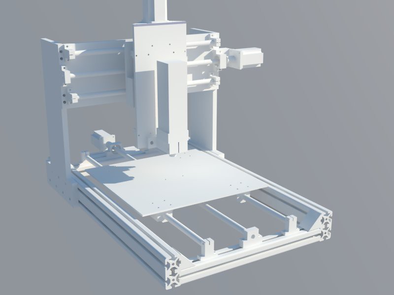
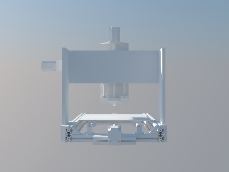
Hi guys, below are some images and renders of my first proposed CNC machine. I intend to do a small amount of aluminium and wax routing, but mostly I intend to use this to aid in the manufacture of speaker cabinets and PCB milling.
I've just posted an RFQ over in the other forum asking for quotations on getting some of the parts made up.
Cutting area is 400mm x 400mm and the parts I intend to use include:
Ballscrews all around
Kress 1050-1 FME
Valuframe extrusion
Gecko 540 stepper driver
For the stepper motors i'm not sure, but I was looking at these: http://cgi.ebay.co.uk/3-Stepper-Moto...7#ht_535wt_911. If I understand correctly, even though the motors require 4.2A and the gecko only provides 3.5A, this would mean that the motors just run at reduced torque, and wouldn't damage them, or the controller. Please correct me if i'm wrong.
The only thing I don't like about the design is how far the Y axis stepper motor sticks out. I was originally looking at setting the motor in the upright support and using a timing belt/pulley combo, but i'm not sure i'm willing to deal with the extra cost and potential increased backlash for the sake of aesthetics.
7 by SgtSiff, on Flickr
4 by SgtSiff, on Flickr
3 by SgtSiff, on Flickr
2 by SgtSiff, on Flickr
1 by SgtSiff, on Flickr
5 by SgtSiff, on Flickr
Thanks for looking.

 Reply With Quote
Thread Information
Users Browsing this Thread
There are currently 1 users browsing this thread. (0 members and 1 guests)
Similar Threads
-
BUILD LOG: New Build - For Your Amusement - MK-2 build
By Karl in forum DIY Router Build LogsReplies: 12Last Post: 08-02-2017, 08:03 PM

Bookmarks