Thread: Siff' Build Log
Hybrid View
-
04-08-2011 #1
Update time!
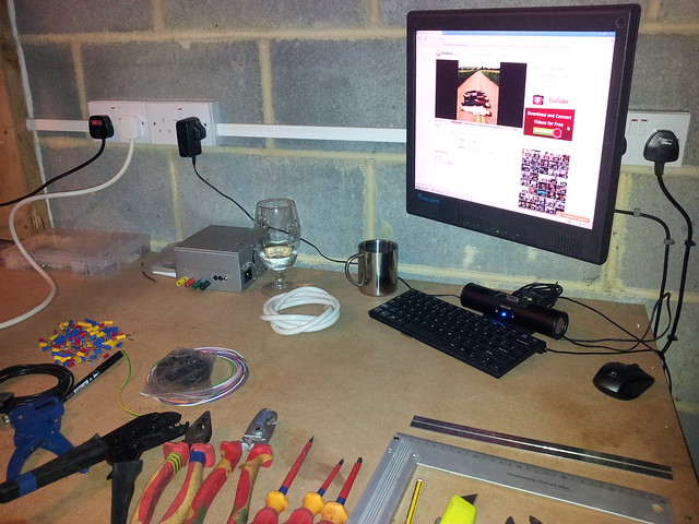
Rails etc haven't arrived yet so I've been busy getting my garage ready. It was empty before, so I've built a workbench and put it on it's own RCBO protected ring. I also got my workshop PC set up:
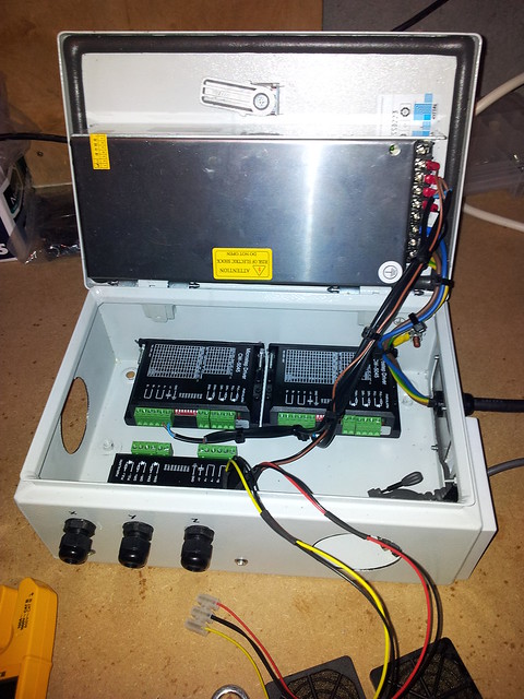
My steppers/drivers have arrived so I began creating my box of electrickery! :dance: These are all terrible photos by the way (taken on camera phone with a sprinkling of couldn't be arsed) I don't have any progress photos just the almost finished box:
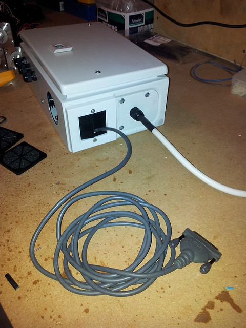
My homemade 24v/5v power supply for the cooling fans and breakout board:
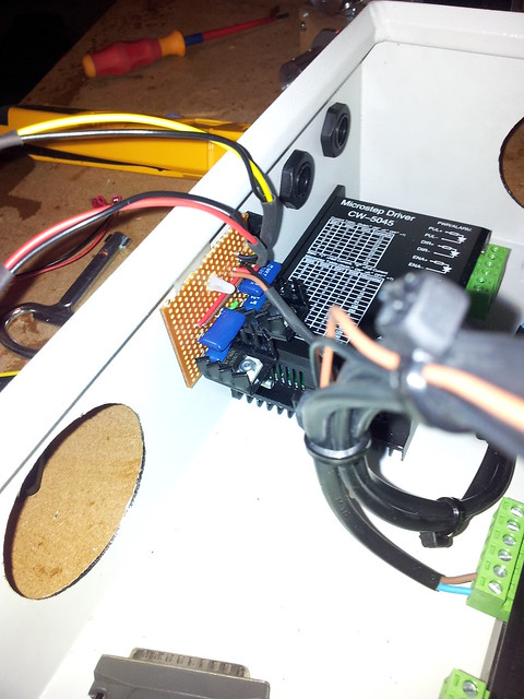
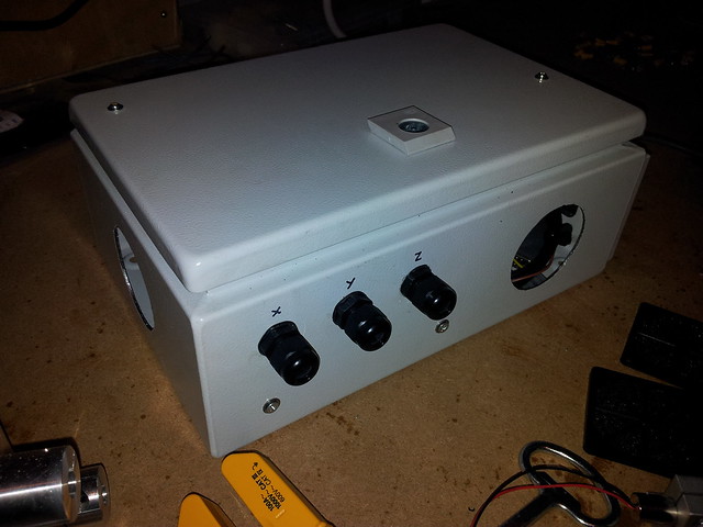
This shot shows the almost finished box except for the cooling fans because they haven't arrived yet. The stepper drivers have been bolted to the case and are covered in thermal paste where they make contact. You can also see my line laser on this shot, which is going to be for my 3D scanner project. Fans + Filters will be attached on the outside.
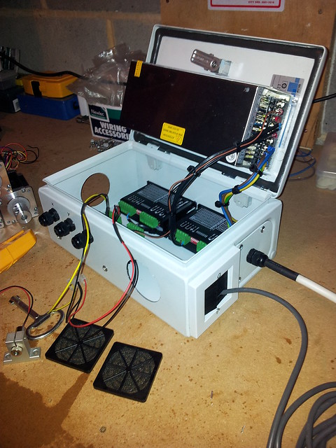
I'm still waiting on the breakout board and E-stop switch, which will be fitted in/on this case.
I've used glands and filters on all openings to keep dust out. The only possible place for dust to get in is the brush plate at the bottom, it will keep 99.9% of the dust out though so i'm happy.
I've also got a homebrew temperature sensor gizmo, that will let me know if the case is getting too hot. I doubt this will happen because, erm, well, it just won't! :)
Also, I've only got a baby pillar drill so I couldn't get the case under to drill those 60mm holes... they were a pain in the Harris to cut by hand and my baby walty almost burned out!
Thankya, goodnight, much lav!
-
08-08-2011 #2
Hi guys, just wondering if I could get some help. I can't seem to get my steppers to turn via mach 3. I know the motors are wired up correctly becuase I tested by shorting enable and the simulating pulses with a link wire and they turned just fine.
I've set up the correct port and pins in mach 3 (or so I think!), but it is as if it can't see the breakout board? The emergency stop button doesn't do anything and I don't know where to start looking... I don't know if I was doing it right, but I resetted the software on mach3, went to diagnostics and it showerd all 3 enables were on. I tested between the gnd pin a pin 1 on the parallel port and got nothing? I am howerver getting around 4v on on pins 12, 11 and 10.
Cheeers
-
08-08-2011 #3
What breakout board do you have? Does it have a charge pump and if so is it configured? You don't need to do anything with the enable inputs.
-
09-08-2011 #4
Hi, it's this breakout board:
http://www.zappautomation.co.uk/zp5aint-p-499.html
It's being run from a regulated 5v supply, I don't know if it has a charge pump
Didn't have time to recheck all of my wiring but i'm going to have a fiddle tonight.
Some good news though, my spindle arrived today! Seems excellent quality and I can't wait to get it fired up after i've configured it. Does anyone put anti freeze in their water to aid in cooling/ add corrosion resistance?
Cheers, Joe
-
09-08-2011 #5
Doesn't look like it has a charge pump...
http://www.slidesandballscrews.com/p...d%20manual.pdf
You should put something in the water to stop corrosion / algae etc. I've not yet but will do soon.
-
12-08-2011 #6
I've taken a break from getting the drivers to work to re-think (again!) my cnc layout, I came up with the design below. What do you guys think? The Y axis is more secure and lower down, the end plates are more substantial and will have 4 x m8 fixings each and the aluminium rail is 60 x 60 all around. I haven't added in the Y axis ballscrew yet but I think i'll put it along the top. I've also used one solid piece for the back-plate which will hopefully add a bit more strength. It needs it.. All my rails arrived yesterday and I didn't realise how heavy they all were combined :confused:
-
12-08-2011 #7
Looks much better to me.
Putting the Y-axis ballscrew along the top is not a good place since it's so far from the cutting force. The Y-axis bearings obviously don't provide any support parallel to the Y-axis, so they would be pushed slightly in that direction. If the screw is lower down it's less of a problem. The best place would be to put it on the opposite side, but that's a bit in the way...
Not sure about the way you've mounted the X-axis linear bearings. Though the forces might by more even, it's much much harder to get them parallel. I'd keep the orientation you had previously. I think it's best to have them that way anyway as the forces are not even - you've got the weight of the gantry loading them in one direction.
Thread Information
Users Browsing this Thread
There are currently 1 users browsing this thread. (0 members and 1 guests)
Similar Threads
-
BUILD LOG: New Build - For Your Amusement - MK-2 build
By Karl in forum DIY Router Build LogsReplies: 12Last Post: 08-02-2017, 08:03 PM
Bookmarks