
Thread: Myford VM-B CNC Conversion.
-
04-10-2011 #1

 Last Activity: 23-09-2017


So got most of the big bits of a VM-B from the Myford sale for £100.
Brand new but well shop soiled and robbed.
No motor, spindle, pulleys, covers etc
Main bits are base, saddle, bed, screws and head.
problem is this is a right backwards arsed design as where the spindle locates.
Rough assembled with a lump of tube to represent the missing spindle.
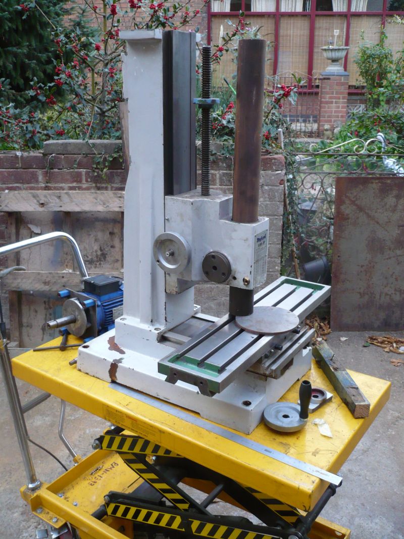
Right at front of travel with a plate on bed that it will need to machine, plate is 150mm or 6"
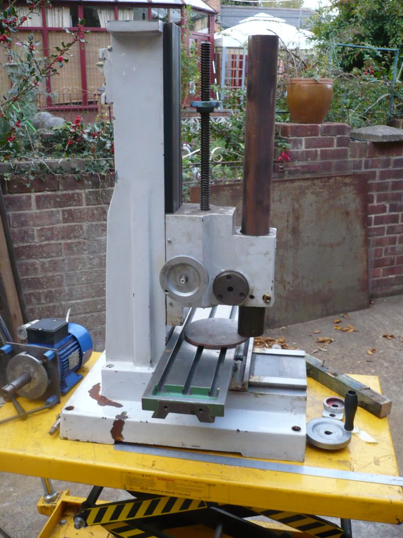
Full back and it overhanging the bed.
Shot inside the head showing how cored it is, no spare metal anywhere.
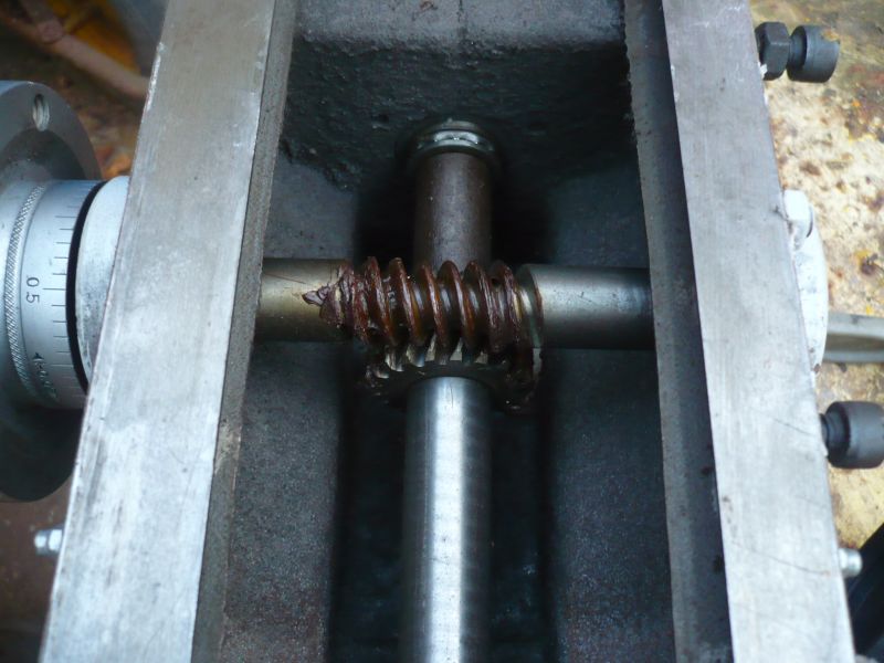
I can squeeze another 15mm to give me 165mm but the problem is the spindle hole is in the wrong position, plus I don't have a spindle anyway or any of the drive mechanism.
So this is the bit that poses the problem.
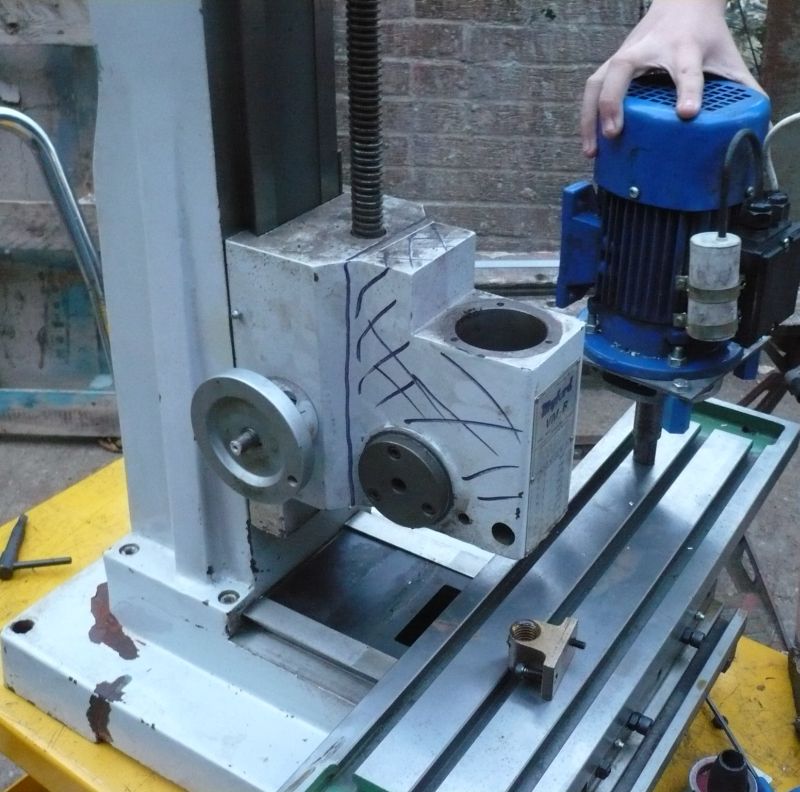
So a bit of hacksawing, not shown, a bit of angle grinding, definitely not shown due to artisic license and a bit of surface grinding.
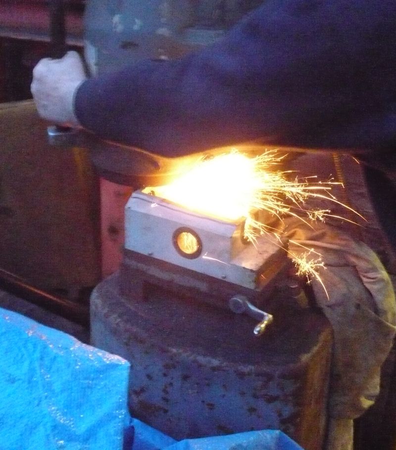
Only shown because they show it on tele and it's only microns being killed <g>
And we get this:-
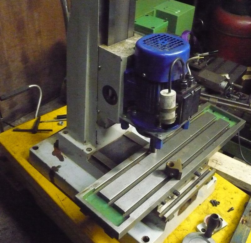
The motor in the picture is only a slave for pics, new motor ordered.
After searching all the motor specs we can get a 1.1Kw [ 1.5HP ] motor in a reduced 80 frame size at 2800 rpm [ remember we are on 50 Hz ]
80 Frame means 80mm from feet to centreline, that one in the pic is a 63 frame.
So if we run a 2 pole motor at 120 hz which they will stand, they are good for 6,720 which is about the right speed for a 3mm drill.
At low speed usuable torque on a 1.1Kw motor is about 20 Hz giving a low speed of 1,120 rpm.
Not much use for a manual machine but for a CNC only using small cutters this spread is ideal.
So plan B is to strip the new motor when it comes, make a new end up out of solid alloy as most motor ends now and very skimpy, fit a double row angular contact bearing that held in place by a keep plate.
Press the shaft out and make a complete new shaft to take ER 20 collets, because the bearing won't be able to go over the collet chuck bit the rotor will have to be modified to be a push fit, not press fit and have a keyway and retaining nut to hold it in position.
Many grinder rotors are built this way.
Get the rotor re-balanced and rebuild the motor.
motor then bolts to a conversion plate between the cut down head and the motor.
Ballscrews are on order from China, motor should be here later this week or early next week.John S -
-
04-10-2011 #2
 Last Activity: 5 Hours Ago

Seen this on HSM the other day, and was wondering how you were going to get it to work.
Got to love abit artistic license :heehee:
-
06-10-2011 #3
 Last Activity: 24-03-2022
nice one, looks like a nice sturdy lump of iron... itll be interesting to see how well one of those double row A/C breaings holds up to some heavy work
are you saying your going to make the ER20 chuck or are you somehow adding one to your new shaft ?
-
06-10-2011 #4
Last Activity: 23-09-2017
Mark,
Press the shaft out of the motor and make a complete new shaft with integral ER20 collet chuck. Plus a new drive end housing to take a better bearing and a bit more substantial.
Hopefully motor will be here tomorrow and I can get it stripped and measured up. I can only work on this two nights a week, Tuesday and Friday as I'm doing it with my grandson as a design project, unfortunately I won't be able to order the bearing until the motor gets here as I don't know which one is fitted, I'm guessing a 20mm bore but it may be a 25mm bore.
Mind you nothing to stop going up to 25 which I may well do. Watch this space for a Friday update.John S -
-
06-10-2011 #5
Last Activity: 24-03-2022
Splendid !
if you find the time will you take some photos etc... im wondering how you will go about getting an accurate inner face/seat, for the collets
what material are you going to use ?
im sort of guessing you will do a grind with the motor running once the shaft/collet chuck and motor are assembled ?
-
06-10-2011 #6
Last Activity: 23-09-2017
Mark,
Should be plenty of photos as Grandson needs all this for his project CV thingy.
Done a few of these previously and quick run down is to strip the motor and take measurements mainly where the rotor needs to sit.
Then draw up a new front cover to take the bigger bearing and that will then define where everything goes.
Old shaft is pressed out of the rotor and a keyway broached in. New shaft will be made a slip fit and rely on the keyway and a retaining nut on the tail side of the rotor.
New shaft roughed out of a piece of EN19 steel, couple of mm left on all over.
Hold by long diameter and machine where the ER20 fitting goes all at one setting, bore at 8 degrees and blue fit to suit collet, screwcut M25 x 1.5 p to suit nut.
Remove from chuck, replace with lump of Scrapbinium [ TM ] and turn down to 13mm by 40mm long, polish for good finish.
Then very carefully insert 13mm collect into the nut and tighten up onto the shaft you have just turned. running at low speed ~150 rpm, carefully centre drill the opposite end, use low revs so it doesn't whip.
Once the centre is in then the rest of the bearing diameters, rotor diameter and retaining thread can be finish turned and polished to size.
Do a build up and spin by hand checking the runout of a test bar held in the collet, should be minimum run out.
Strip and send new spindle for Tuftriding this is a heat treatment that is done at about 400 degrees and not hot enough to cause distorsion. it only puts a very thin skin of hardness on but enough to protect it against normal wear and tear, EN19 suits this process very well. Another plus is that it's virtually rust proof.
Short of hardening full out and then having all surfaces ground afterwards to ensure they are true this is the easiest / best way to produce a spindle.John S -
-
The Following User Says Thank You to John S For This Useful Post:
-
07-10-2011 #7
 Last Activity: 05-04-2020
Where do you get the EN19 steel from? I'm guessing it would be the right stuff to use for ATC holders.
-
07-10-2011 #8
Last Activity: 23-09-2017
McCreadies at Rugby, or used to be, then called Niagara and can't remember what they are called now.
Phone number is in workshop.
Just done a search, now called Acenta Steel
http://www.acentasteel.com/distribut...cts/index.html
Alloy steels in second column down RH side. Just noticed that they now only do EN19 in 80mm diameter upwards, so if i had to buy some I'd go for EN16M or EN24, both would be suitable.
In fact for a home shop EN8 would be fine and it machines like butter.John S -
-
07-10-2011 #9
Last Activity: 24-03-2022
nice one john, looking farward to this one :)
-
08-10-2011 #10
Last Activity: 23-09-2017
Next instalment, as I said this is only being done on Tuesdays and Fridays as it's the only time my Grandson can get down.
Still awaiting balls crews etc so got the motor today.
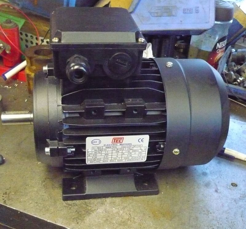
Bog standard 1.1kw, 1.5 HP motor and stripped it down, nothing to these, cover off, fan off and an end shield then pop the rotor out.
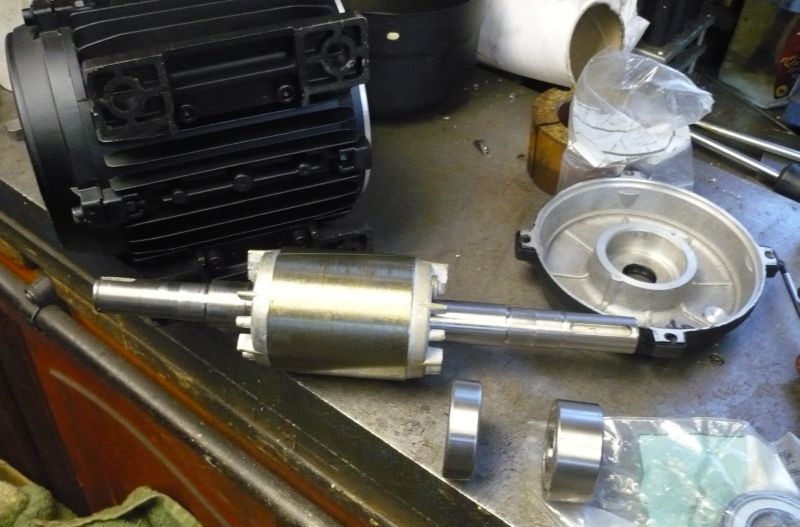
Original bearing on left, similar but double row angular contact on right.
One thing to note with these new inverter metric framed motors is the absence of slots in the rotor. These are now coming out with the allow 'winding' pressure die cast into internal slots so the outside of the laminations is uninterrupted, less chance of flying out at high speed.
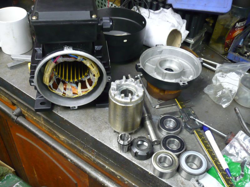
Shaft pressed out the rotor, keyway broached in and set around the rotor are the existing bearings, two different sized angular contact bearings, existing 20mm and the one I'm going to use at 25mm bore plus a collet and nut for ER25.
I was going to use ER20's but on checking I don't have collets for ER20's so it was a choice of 16's, 25's or 32's so 20's won out.
Next step is to make drawings up of the existing motor so the details can be transposed without cutting metal. This is the existing motor as an accurate drawing.
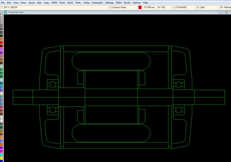
Drive shaft is on the right.
Same drawing with the modified nose superimposed on it.
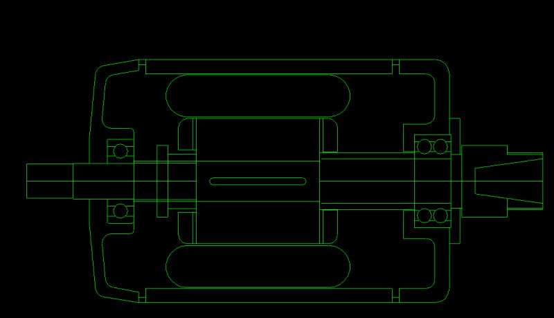
Because the bearing can't go on over the collet nose it's designed to assemble the opposite way and the bearing is held into the front cover by a keep plate so it's held firm with no end float.
This means the rotor will have to assemble onto the shaft after hence the keyway for a sliding fit as opposed to a press fit and a nut on the fan end to secure it all.
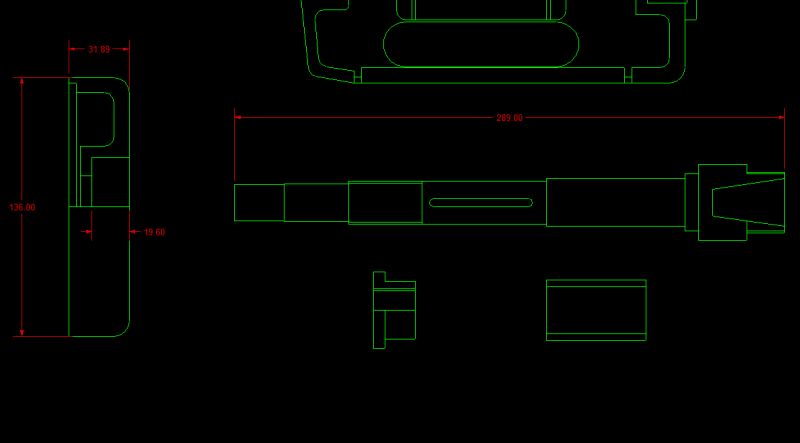
Next job is to copy the spindle, spacer, nut and end cover from the second drawing and dimension up [ only part done so as not to crowd the drawing ] We now have all the details we need to start making the spindle on Tuesday.Last edited by John S; 08-10-2011 at 01:48 PM.
John S -

 Reply With Quote
Thread Information
Users Browsing this Thread
There are currently 1 users browsing this thread. (0 members and 1 guests)
Similar Threads
-
NEW MEMBER: Hi from Denbigh North Wales - Myford ML7 lathe conversion beginner
By veedub1955 in forum New Member IntroductionsReplies: 6Last Post: 27-04-2012, 11:58 AM -
cncyour myford
By bobfly in forum Milling Machines, Builds & ConversionsReplies: 0Last Post: 26-02-2012, 01:34 PM -
CNC Myford ML7
By croy in forum General DiscussionReplies: 0Last Post: 28-05-2011, 07:40 AM -
Myford A5 topslide.
By stephentanks1 in forum Lathes, Lathe Rebuilding & ConversionsReplies: 1Last Post: 18-04-2010, 08:03 PM

Bookmarks