
Thread: CNC design for consideration
Hybrid View


-
10-04-2012 #1

 Last Activity: 24-03-2022


 told you it would be silly not giving him a shout :)
 Originally Posted by jonbabbz

only three screws ?? if you are not using two screws on your x axis id have a good think about the implications before you press buy
that extra screw will more than earn its keep!
your design shows four screws? have you already got one for your Z axis?
-
10-04-2012 #2
 Last Activity: 23-09-2017

That sounds OK to me, as I said before he's 110% genuine.
John S -
-
10-04-2012 #3
Last Activity: 23-09-2017
Sorry, didn't realise it was illegal for a company to try to make a bit of money.
You could always collect from ChiJohn S -
-
01-05-2012 #4
 Last Activity: 28-08-2013
Originally Posted by John S
Last Activity: 28-08-2013
Originally Posted by John S
Anyone got an address for Chai? PM please. (EDIT: Thanks, got it now)Last edited by mocha; 01-05-2012 at 10:34 PM. Reason: info rcvd
-
16-05-2012 #5
 Last Activity: 12-03-2021
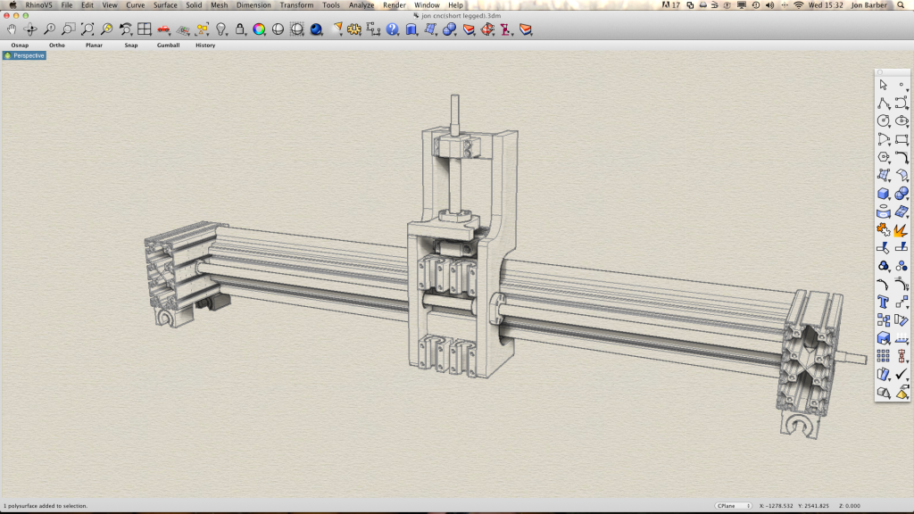
Hi guys, been really busy lately so updates will be few and far between. Im collecting my parts together at the moment but just wanted to show you a revised y and z axis on my machine and see what you think. Ive moved the rails above and below and gone for supported on z. Ive tried to make z as light and thin as possible so I can get more movement on y. As for the previous design LotusPack, it is driven from both sides you just cant see it because of the angle of the drawing that's all. I considered going for profile rails but I don't want to spend that amount on a first build. Maybe the next one ;)
-
16-05-2012 #6
Last Activity: 18-05-2012
Hi CNC design firend, this looks really good, have a few points to consider on your design: Originally Posted by jonbabbz
1) The Y Axis is very close to the X axis (A), going on the diagram there seems to be little space under the X axis for your work piece, (Work Area my sketch) if the Y axis bearing is level with the work table.
2) The Z axis feed drive plate is working outside the bearing range (C), 4 bearings below the Z leadscrew
3) Can't quite see how the Y axix bearings will work (D) assume there are two bars 1 top and 1 bottom
4) It would be better to increase the X axis bearing distance (B) at each end, the wider the stronger, although you will lose some travel distance.
Attachment 5993
The tool stress area is best kept inside the bearing array, if possible.
hope it goes well...
-
16-05-2012 #7
Last Activity: 05-04-2020
 1) The bed is well below the X-rails and presumably its height will be adjustable. Having that distance as small as possible is excellent to maintain rigidity. Originally Posted by LotusPack
2) That shouldn't make a difference.
4) Yes it would be better to space the X-bearings out more. What is their current spacing?
-
10-04-2012 #8
Last Activity: 12-03-2021
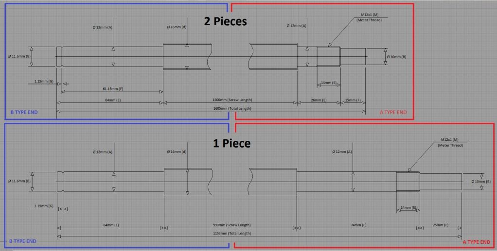
So its all ordered then! Very nice guy. He sent me the standard drawings for the machined ends and I had a peruse to see if they would fit my machine and wouldn't. So I simply emailed him my requirements and he has not charged me anything extra! I will definitely do business with him again. The screws I ordered are just for x and y. i need to redesign the z axis because I'm not sure I want to go with round rail. I think there will be too much deflection at the cutter so ill just buy another smaller ballscrew when I'm ready for it. I want to change the bed too. Here's what I ordered screw wise. I'll create a build log when I get all my parts together. Can't wait :)
-
01-05-2012 #9
Last Activity: 18-05-2012
Hi The Y axis looks like it is set on one side; if it is, this will jam as the axis drive needs to be central or with two stepper drives simultaneously operated one on each side of the machine. I would also consider widening the Y axis bearings so the machine has less Y wobble. As you are only cutting MDF and Plywood accuracy is not an isse here that design is good enough. If you can squeese a bit more out of your budget, go for the linier bearings as in the photo. Originally Posted by jonbabbz
These are far more accurate and rigid and will increase rigidity and production speed. Keeping this design square in the X & Y plane is going to be dificult.
-
16-05-2012 #10
Last Activity: 18-05-2012
- Ah yes, I see, that sounds good.
- Ok cool but the further away the Z plate drive point is from the bearings the more compound the tolerance will be on the drive forces. You are right it should not affect the travel accuracy.
The Z axis travel looks quite short compared to the X&Y if you are designing for large surfaces and need to jump up and down the job work plane will this have enough for your need? I originally had 250mm Z distance and have since increased to 400mm for those extra long tools and thicker jobs. My Z axis runs from the collet face at 20mm above the table to 420mm +Z my machine has a fixed 200mm throat under the gantry. This now allows for quite a long tool for example drilling through 200mm you obviously need at least 410mm travel. As the -Z movement starts to put the pressure on when drilling the whole gantry structure starts to go under stress, which is why I advocate centering the spindle in middle of the Y axis bearings, if it is off centre the gantry start to tilt back against all those bearing tolerances and pulls the drill out of square and jams up the drill.
I have a distance of around 400mm between the bearings on a 1.3m Y axis total length so I get an affective length of approx 900mm which is perfect for the standard linear scale I have fitted.
This is a good design as most fixed table machines have the "Throat" restriction under the gantry. How are you going to adjust the table up and down and keep things square? I would think a secondary Z knee adjustment for the work piece height, suggest a manual mechanism that can be locked after part fitting otherwise although flexible just like a knee milling machine, will bring in further rigidity issues.

 Reply With Quote
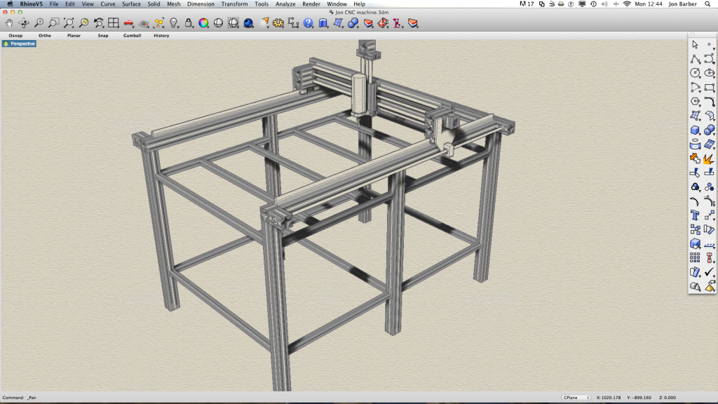
Thread Information
Users Browsing this Thread
There are currently 1 users browsing this thread. (0 members and 1 guests)
Similar Threads
-
Interesting Papers on heavy duty design, vibrations, composites and column design
By D.C. in forum Gantry/Router Machines & BuildingReplies: 15Last Post: 25-06-2016, 10:13 PM -
Design Help Pt2 Required for CNC design/Build
By MikeyC38 in forum Gantry/Router Machines & BuildingReplies: 38Last Post: 21-07-2014, 02:05 PM -
RFQ: Pre-RFQ Design
By Hutchie in forum Projects, Jobs & RequestsReplies: 11Last Post: 05-02-2012, 06:45 PM -
Design help etc required with DIY CNC Router Design / Build
By MikeyC38 in forum Gantry/Router Machines & BuildingReplies: 12Last Post: 21-10-2011, 04:50 PM

Bookmarks