
Thread: CNC design for consideration
Threaded View


-
01-05-2012 #18

 Last Activity: 18-05-2012

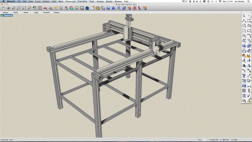
 Hi The Y axis looks like it is set on one side; if it is, this will jam as the axis drive needs to be central or with two stepper drives simultaneously operated one on each side of the machine. I would also consider widening the Y axis bearings so the machine has less Y wobble. As you are only cutting MDF and Plywood accuracy is not an isse here that design is good enough. If you can squeese a bit more out of your budget, go for the linier bearings as in the photo.
 Originally Posted by jonbabbz

These are far more accurate and rigid and will increase rigidity and production speed. Keeping this design square in the X & Y plane is going to be dificult.

 Reply With Quote
Thread Information
Users Browsing this Thread
There are currently 1 users browsing this thread. (0 members and 1 guests)
Similar Threads
-
Interesting Papers on heavy duty design, vibrations, composites and column design
By D.C. in forum Gantry/Router Machines & BuildingReplies: 15Last Post: 25-06-2016, 10:13 PM -
Design Help Pt2 Required for CNC design/Build
By MikeyC38 in forum Gantry/Router Machines & BuildingReplies: 38Last Post: 21-07-2014, 02:05 PM -
RFQ: Pre-RFQ Design
By Hutchie in forum Projects, Jobs & RequestsReplies: 11Last Post: 05-02-2012, 06:45 PM -
Design help etc required with DIY CNC Router Design / Build
By MikeyC38 in forum Gantry/Router Machines & BuildingReplies: 12Last Post: 21-10-2011, 04:50 PM

Bookmarks