
Thread: CNC design for consideration
-
16-05-2012 #21

 Last Activity: 18-05-2012

 Hi CNC design firend, this looks really good, have a few points to consider on your design:
 Originally Posted by jonbabbz

1) The Y Axis is very close to the X axis (A), going on the diagram there seems to be little space under the X axis for your work piece, (Work Area my sketch) if the Y axis bearing is level with the work table.
2) The Z axis feed drive plate is working outside the bearing range (C), 4 bearings below the Z leadscrew
3) Can't quite see how the Y axix bearings will work (D) assume there are two bars 1 top and 1 bottom
4) It would be better to increase the X axis bearing distance (B) at each end, the wider the stronger, although you will lose some travel distance.
Attachment 5993
The tool stress area is best kept inside the bearing array, if possible.
hope it goes well...
-
16-05-2012 #22
 Last Activity: 05-04-2020


 1) The bed is well below the X-rails and presumably its height will be adjustable. Having that distance as small as possible is excellent to maintain rigidity. Originally Posted by LotusPack
2) That shouldn't make a difference.
4) Yes it would be better to space the X-bearings out more. What is their current spacing?
-
16-05-2012 #23
Last Activity: 18-05-2012
- Ah yes, I see, that sounds good.
- Ok cool but the further away the Z plate drive point is from the bearings the more compound the tolerance will be on the drive forces. You are right it should not affect the travel accuracy.
The Z axis travel looks quite short compared to the X&Y if you are designing for large surfaces and need to jump up and down the job work plane will this have enough for your need? I originally had 250mm Z distance and have since increased to 400mm for those extra long tools and thicker jobs. My Z axis runs from the collet face at 20mm above the table to 420mm +Z my machine has a fixed 200mm throat under the gantry. This now allows for quite a long tool for example drilling through 200mm you obviously need at least 410mm travel. As the -Z movement starts to put the pressure on when drilling the whole gantry structure starts to go under stress, which is why I advocate centering the spindle in middle of the Y axis bearings, if it is off centre the gantry start to tilt back against all those bearing tolerances and pulls the drill out of square and jams up the drill.
I have a distance of around 400mm between the bearings on a 1.3m Y axis total length so I get an affective length of approx 900mm which is perfect for the standard linear scale I have fitted.
This is a good design as most fixed table machines have the "Throat" restriction under the gantry. How are you going to adjust the table up and down and keep things square? I would think a secondary Z knee adjustment for the work piece height, suggest a manual mechanism that can be locked after part fitting otherwise although flexible just like a knee milling machine, will bring in further rigidity issues.
-
16-05-2012 #24
Last Activity: 12-03-2021
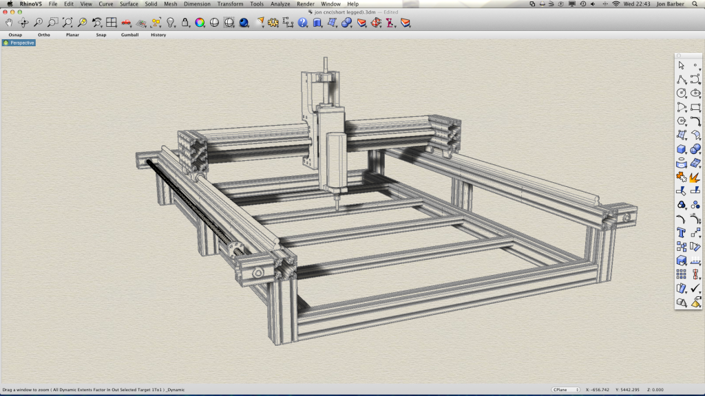
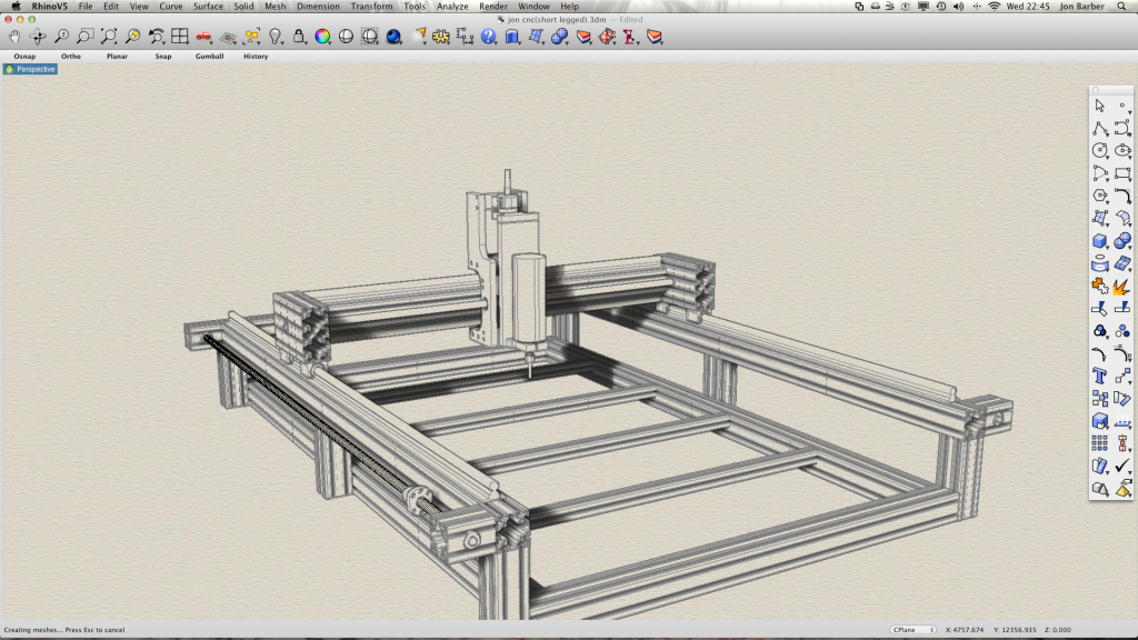
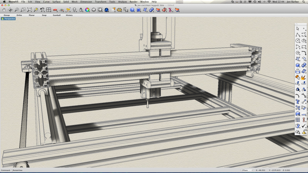
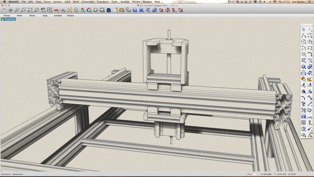
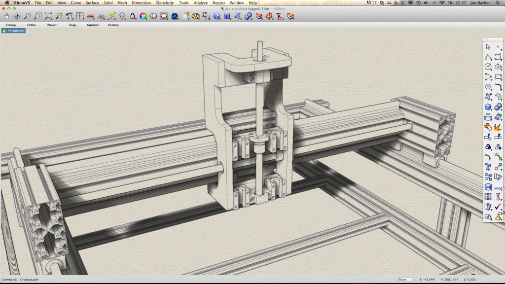
The table is going to be fixed but I have left room for sacrificial packing on the workspace to build it up if need be. The point about widening the bearing spacings was on my to do list and has now been done. The z axis question im not quite sure I understand what you mean. Here are a few more pics to show exactly how it is in its entirety. I have yet to put a lot of holes and strengthening brackets on but I can do that as I go along with the build. I will be moving onto building the z axis next week :)
Z AXIS DOWN
Z AXIS UP
Y Bearings and rails
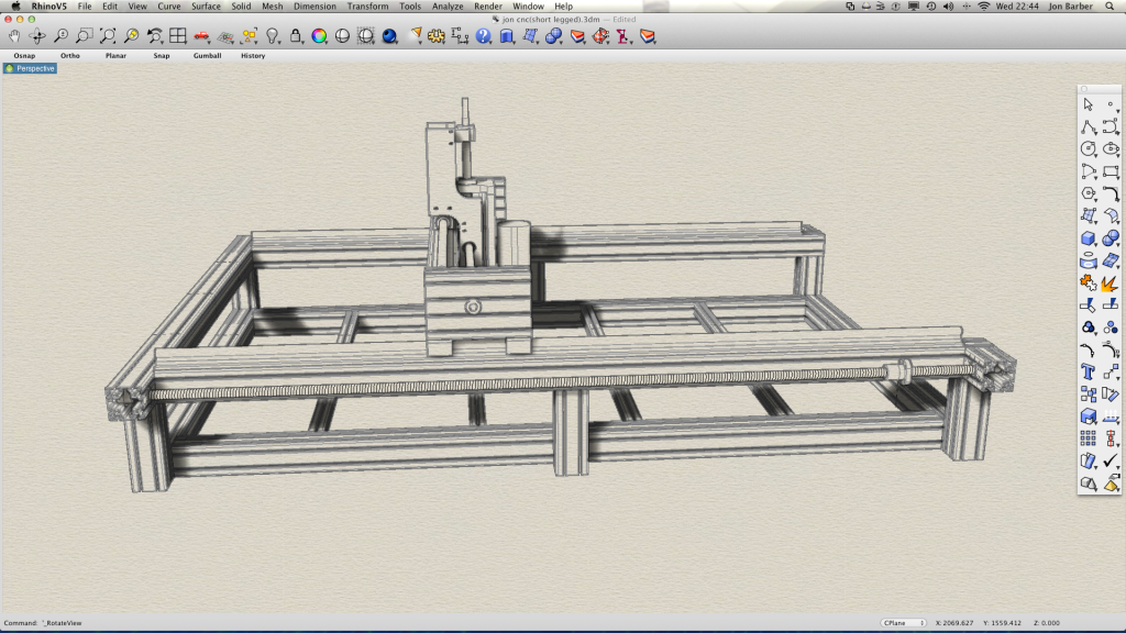
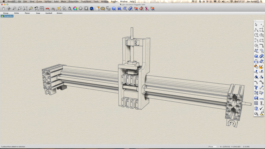
Side View
-
16-05-2012 #25
Last Activity: 05-04-2020
You've done well to get the Z-axis that narrow, but the problem is the Y-axis bearing spacing is now too small. Forces parallel to Y will tend to twist the Z-axis, so you need the bearings spaced out further to resist this. Clearly you'll have to either sacrifice travel or make the frame wider, neither of which is ideal but that is surely better than the whole machine being compromised for the sake of a bit more travel on Y?
-
17-05-2012 #26
Last Activity: 12-03-2021
So what spacing would you suggest Jonathan? It's a valid point but I would have thought any forces trying to twist it on the y axis would be counteracted by the bearing diagonally opposite as it is. Obviously bigger spacing would make it more durable, but I can't widen the actual machine any more as I already have my screws and rails. I guess I'll just have to sacrifice travel on y.
Last edited by jonbabbz; 17-05-2012 at 08:54 AM. Reason: Spelling
-
17-05-2012 #27
 Last Activity: 24-03-2022
i would at least try to fit them flush with those side plates... the tool deflection forces are not your main worry, what would worry me is resonance Originally Posted by jonbabbz
Last Activity: 24-03-2022
i would at least try to fit them flush with those side plates... the tool deflection forces are not your main worry, what would worry me is resonance Originally Posted by jonbabbz
if the resonance from cutting finds the sweat spot on your Z the forces will be masive compared to the cutting force and will result in a crap finish
it may only take a little extra stiffness in a design to prevent your typical router resonance getting a grip.... so in my opinion, every tiny little bit of stiffness you can squeeze out of the bugger will pay
imagine you push on a lamp post... your not going to cause it any mischeif... then you push and pull the lamp post with the same force in a opportune rhythm you can get close to wrecking it... with this in mind the problem becomes a little more stark
in an ideal world i guess you would space your bearings at least as wide as you have them tall and if not, as wide as you can
-
17-05-2012 #28
Last Activity: 18-05-2012
Hi Jon,
These are all point of ease of use really.
Now I see the whole picture, you have addressed quite a few limitations on standard design for rigidity, etc. But there is always a compromise on access and travel distances. I can also see there is room for linier gauges if you want them later.
Because of the limit or gap between the bed and under the gantry, I am assuming that the Z axis travel to the bed is 200mm for my example, 2nd picture shows the tool down. Now looking at the first picture, tool up, the travel is only going to be as high as the Z ball screw length. So my suggestion is to double the bed to gantry gap size and use that as the ball screw length (400mm). This will allow you to use long tools that need to machine through the 200mm. So the Z ball screw needs to be 400mm to cater for the machine dimensions.
One other point on the use of the machine, being as you will have to work over the Y axis rails for job setting it could be quite difficult to set a job “inside this area”. Also as the machine has sides if you have a larger piece of work there needs to be an opportunity to hang the work over the edge. The X axis should be ok for long jobs and you have given enough to push the work through the X axis and machine the next section providing you leave the gap at the back. I have just recently machined a kitchen cooker hob aperture in a very long worktop, much bigger that the machine length. The Y is always a restriction so I made sure I could cope with at least 700mm so I can cut outside the standard 600mm units on the machine Y length. Your design seems to handle all this ok.
The last picture “Side View” shows the elevation on the bearing widths quite well; there you can see the spindle in line with the front Y bearing, this is where you could increase the end piece length to move that bearing to the same distance as the one at the back from the spindle centre and give yourself a equal pressure on these bearing in the Z axis when tool pressure is applied. I know that will reduce the Y axis working distance. You have said that this point was already on you to do list and now done. :-)
How are you going to set, adjust and maintain the X, Y and Z squareness?
The nice thing about two Y axis ball screws is you could independently adjust to fine tune the X and Y squareness. The Y Z plane can be adjusted ok using the fixing into the end pieces but need to consider how to adjust the X Z plane as this will be dependent on the construction. It may be worth thinking about this because when finished getting it all square can be a nightmare of rebuilding with shims, etc. This of course depends how accurate you want is all to be. Of course you could bolt it all together and it may come out spot on for you, in my experience a Gantry Mill is always out of square and needs some mechanism for fine adjustment.
Other minor points
Another spindle (Motor) brace at the top of the motor
Axis stepper cable management particularly for the X behind the gantry
It is looking good, nice CAD what do you use?
Regards
-
17-05-2012 #29
Last Activity: 12-03-2021
It does make sense to space them out with regards to resonance. This is the reason I wanted a second opinion, thank you. The z travel is only 90mm now. I was going to go for a longer travel but decided to keep it simple for a first build. Squareness shouldn't really be an issue as the t slot nuts can be moved/adjusted then tightened so that doesn't really concern me. As I said before, high resolution finishes are not my main goal(I'll be building furniture mainly), but a certain degree is essential. For cable management I'll simply be using a piece of angle aluminium on the back of y with a train on it. There are a lot of items I'll be using that are not on the drawing just yet. I think the biggest mistake was ordering parts before I was completely finished with the design so it kind of limits my adjustments now. Oh well, you live you learn. Nothing that can't be sorted. The cad software is Rhino 5
-
17-05-2012 #30
Last Activity: 12-03-2021
Ok so I think I'm finally happy with it now. Ive done a complete redesign of the z axis and widened it enough so that I can still get the amount of travel in y I need. Ive also managed to get 130mm travel in z doing it this way so it actually works out better. I also wont need to put my existing z ballscrew on the lathe to shorten it :)

 Reply With Quote
Thread Information
Users Browsing this Thread
There are currently 1 users browsing this thread. (0 members and 1 guests)
Similar Threads
-
Interesting Papers on heavy duty design, vibrations, composites and column design
By D.C. in forum Gantry/Router Machines & BuildingReplies: 15Last Post: 25-06-2016, 10:13 PM -
Design Help Pt2 Required for CNC design/Build
By MikeyC38 in forum Gantry/Router Machines & BuildingReplies: 38Last Post: 21-07-2014, 02:05 PM -
RFQ: Pre-RFQ Design
By Hutchie in forum Projects, Jobs & RequestsReplies: 11Last Post: 05-02-2012, 06:45 PM -
Design help etc required with DIY CNC Router Design / Build
By MikeyC38 in forum Gantry/Router Machines & BuildingReplies: 12Last Post: 21-10-2011, 04:50 PM

Bookmarks