
Thread: DIY spindle design
Hybrid View


-
04-12-2008 #1

 Last Activity: 28-10-2019


All good points, Phil, if this were for a precision machine cutting a hard material like steel.
It's going on to a table top router type machine though, intended to cut moulds for composite parts, from mainly EPS foam and MDF. The idea was to make something with a power similar to a small trim router or the larger Dremel type machines, but smaller in diameter, with more robust bearings, a better level of spindle accuracy and, most importantly, a much lower noise level.
If the whole machine turns out to be sufficiently accurate, I may use it for milling/drilling PCBs, although I suspect that the spindle speed will be too low for that task, so I may need to build another, faster, one.
If I get a spindle that is compact, quiet and comparable in accuracy and overall cost to a trim router then it will certainly meet my requirements.
Jeremy
-
10-12-2008 #2
 Last Activity: 04-01-2011
Sorry I must have misunderstood what you meant by:
"I also wanted a fair degree of accuracy, without the fairly horrid run-out that Dremel-like tools have, as I'd like to try using it for milling PCB's as well."
Phil
-
10-12-2008 #3
Last Activity: 28-10-2019
Quite a few PCB routers have been built that work fine with small tools like the Dremel, so my aim was to make something that would be a bit better than this, a bit quieter and hopefully have bearings that would last a bit longer, for around the same price.
I've got a couple of Dremels and the newer one seems to have around 2 thou or so of combined run out and play in the spindle, the older one is quite a bit worse. Their real problem seems to be the eccentricity in the collets, as the tool run out is significantly worse than the spindle - to get the best out of them means re-seating the collet several times to true up the tool. Despite this poor accuracy, many people have shown that they work fine for modest PCB milling, such as the homebrew stuff I'll want to do.
The very best I could hope for using ER type collets is about 1/4 thou TIR, assuming no other error sources, as that's their spec. A 1/10 thou TIR would be totally unachievable using this type of collet chuck, I'd have needed to go for something far more costly if that was my aim.
It's debatable as to whether better than a thou is needed for such an application as DIY PCB milling anyway. Minimum track width is unlikely to be less than about 15 thou and assymetric cutter tip loading isn't an issue for a single flute vee tip PCB milling tool. Given that so many people are very successfuly milling out boards with spindles that are far worse than mine is likely to be I really can't see me having a real problem, apart from the slow speed .
This spindle might be a bit too slow for PCB work with small diameter tools, as it will be limited to around 16,000 rpm. It will be ideal for the bigger mould making requirements I have, using tools up to around 6mm or so, so I may just try it for a while with that task, see how it goes, then look at making a faster spindle for PCB work if I need it.
I've found a source for an ER25 chuck with a 1/2" shaft that looks promising for a future higher speed version. Reducing the shaft size from 20mm to 1/2" gives the possibility of using bearings with a higher speed rating, which will allow me to get up to the 25,000 to 30,000 rpm (or higher) that would be best for the PCB task.
It's good fun experimenting anyway, even if I do get one or two failures along the way.
Jeremy
-
14-12-2008 #4
Last Activity: 28-10-2019
I finished the mechanical part of the spindle today and gave it a test run. All went well, but I need to pull it apart and take a tiny skim from the lower bearing housing, as the lower bearing gets a bit warm after a few minutes running. I noticed that the spindle was a little tight after I assembled it. I hadn't realised how a tiny bit of "pinch" from a bearing pressed into a housing that was very slightly undersized would make such a difference, but it's easy enough to fix.
The good news is that the spindle is reasonably quiet and seems to work well off load. The RC motor didn't even get slightly warm, but the speed controller may need mounting on an additional heatsink, as it was a bit warm after a few minutes running. The motor was drawing around 10 amps from a 12V supply when running flat out, which is a bit high and almost certainly to do with the overly tight lower bearing.
I may also need to adjust the bearing pre-load. I've used a couple of belleville washers under the upper shaft retainer, abutting the top bearing inner race. Pre-load was set by clamping the shaft to compress the bellevilles a small amount, then tightening the shaft collar at the lower end. This wasn't very "scientific", so may also be a contributing factor to the warm running lower bearing.
Here's a picture of the completed spindle:
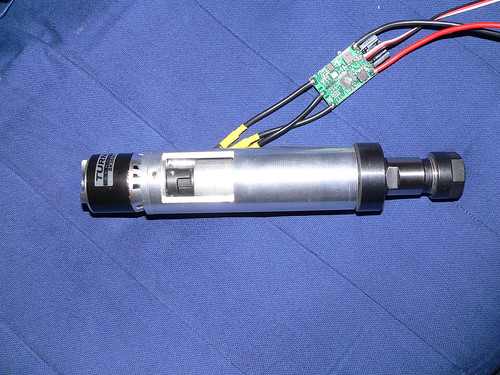
The body is 1.5" in diameter and the overall length is 8.75". The motor outer can at the top (the black bit with the writing on) rotates, so probably needs some sort of guard. The small lovejoy coupling seems to work fine, there's no real vibration at all with it spinning at full chat whilst just being hand-held. Overall it seems to vibrate a lot less than a Dremel and is certainly a lot quieter.
I've done a crude run-out check using a DTI, with it clamped in vee blocks on the surface table. A 3mm carbide cutter shank didn't seem to deflect the DTI at all, which seems pretty good. My DTI isn't really sensitive enough to show anything under about 1/4 thou though, plus the lower bearing is still a bit too tight, so the true run out might be a bit worse.
Nevertheless, if I can fix the lower bearing problem I think I shall be well pleased with this little experiment. Let's hope that the motor turns out to be reliable!
Jeremy
-
23-02-2011 #5
 Last Activity: 12-03-2013
This is very interesting. I've already constructed a gantry type mill and am using a Kress router to mill non-metals. I'm now looking at ways of milling non-ferrous metals and manufacturing a spindle motor for this purpose. One component of the spindle I'm having difficulty sourcing is the actual spindle/collet holder - from where did you get yours please. I've sourced a suitable motor and have decided upon a step-pulley belt drive system in order to achieve good torque at low speeds.
Last Activity: 12-03-2013
This is very interesting. I've already constructed a gantry type mill and am using a Kress router to mill non-metals. I'm now looking at ways of milling non-ferrous metals and manufacturing a spindle motor for this purpose. One component of the spindle I'm having difficulty sourcing is the actual spindle/collet holder - from where did you get yours please. I've sourced a suitable motor and have decided upon a step-pulley belt drive system in order to achieve good torque at low speeds. Originally Posted by Jeremy

-
23-02-2011 #6
Last Activity: 03-11-2020

Hi miopicman , has Jeremy used an air die-grinder as a base for his spindle?
http://www.screwfix.com/prods/38706/...ir-Die-Grinder
Chris
-
23-02-2011 #7
Last Activity: 12-03-2013
I don't think so; have a look at this: http://www.screwfix.com/sfd/i/cat/pdfs/89/p4764389.pdf Originally Posted by ChrisG
-
24-06-2012 #8
Last Activity: 24-06-2012
Have you determined how to pulse the electronic driver for the DC brushless motor?
It should be possible using a 555 timer chip.
SH
-
24-06-2012 #9
 Last Activity: 24-03-2022
servo tester... £2 ish... ebay Originally Posted by sgcharrisoh
Last Activity: 24-03-2022
servo tester... £2 ish... ebay Originally Posted by sgcharrisoh
-
24-06-2012 #10
 Last Activity: 05-04-2020

 Originally Posted by sgcharrisoh
Originally Posted by blackburn mark
Originally Posted by sgcharrisoh
Originally Posted by blackburn mark
Connected to parallel port via PIC development board ... free ish...'acquired' from university.
When I get round to it I'll stick the code on a smaller PIC on a PCB as it's very simple to do and will cost <£1.

 Reply With Quote
Thread Information
Users Browsing this Thread
There are currently 2 users browsing this thread. (0 members and 2 guests)
Similar Threads
-
Interesting Papers on heavy duty design, vibrations, composites and column design
By D.C. in forum Gantry/Router Machines & BuildingReplies: 15Last Post: 25-06-2016, 10:13 PM -
Design Help Pt2 Required for CNC design/Build
By MikeyC38 in forum Gantry/Router Machines & BuildingReplies: 38Last Post: 21-07-2014, 02:05 PM -
CNC Spindle Repair and Spindle Replacement for any Machine of any Manufacturer
By spindeldoctor in forum Manufacturer NewsReplies: 0Last Post: 13-11-2013, 07:50 PM -
Design help etc required with DIY CNC Router Design / Build
By MikeyC38 in forum Gantry/Router Machines & BuildingReplies: 12Last Post: 21-10-2011, 04:50 PM -
My spindle design
By Ross77 in forum Tool & Tooling TechnologyReplies: 22Last Post: 06-08-2010, 06:03 PM

Bookmarks