
Thread: 3-Axis CNC Mill Project
-
25-08-2012 #1

 Last Activity: 13-10-2013


3-Axis CNC Mill Project
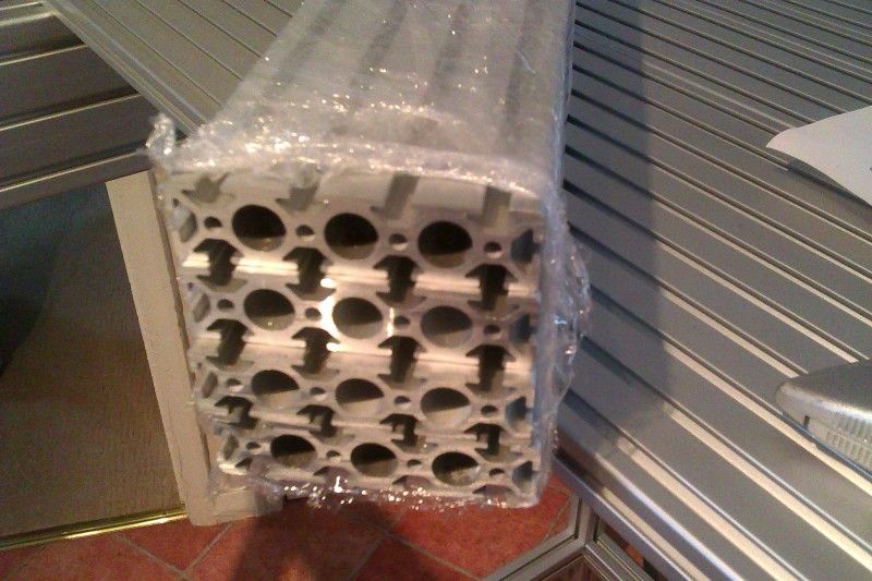
After spending a few weeks contemplating ideas for a new hobby project; then longer deciding on a design I was happy with I finally got my hands on the Aluminium extrusion profile wanted to build the frame.
Aims are to have a complete unit, machine base and storage, 3 axis CNC control with Mach3 software, A3 paper size capability, High precision with zero backlash, hardened linear rails ball screws and stepper motors and finally a special purpose milling spindle.
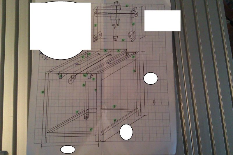
First making a sketch of the idea:
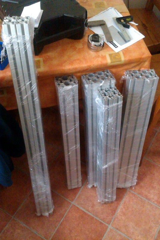
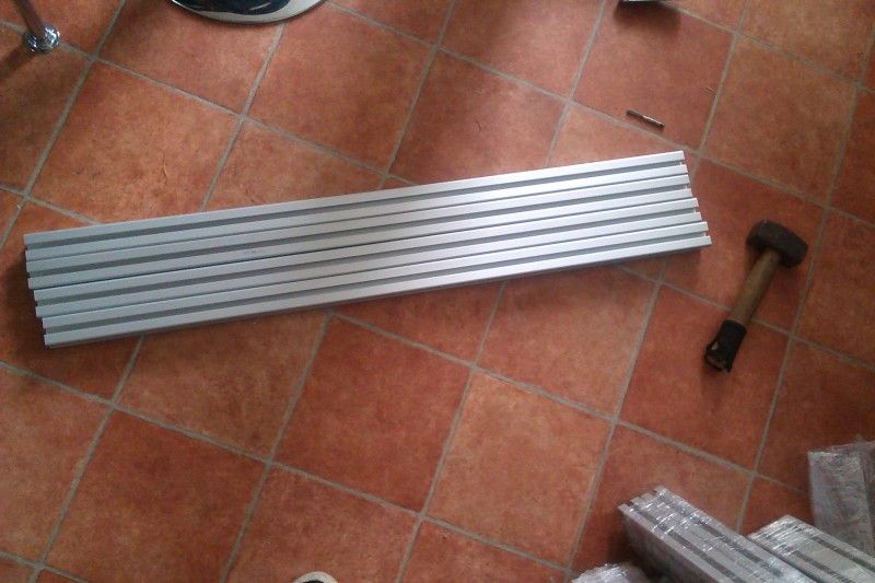
Then realising things look a lot smaller on paper when I get the aluminium home:
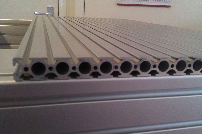
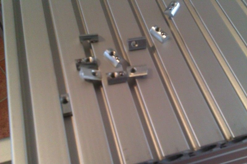
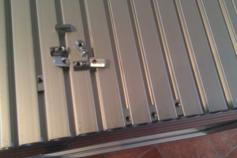
Anyway, first up is to end tap the profiles required M8, thankfully its extruded with the 6.8mm hole required for such:
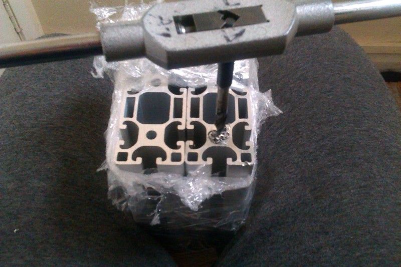
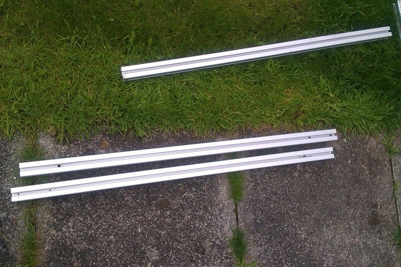
That done:
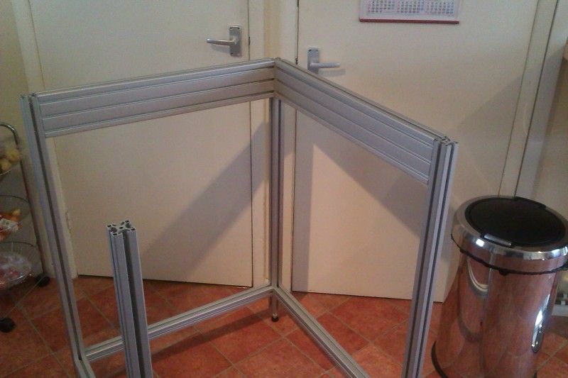
It was on with marking out the holes to assemble the frame:
And then on with drilling them:

Last edited by Jonathan; 27-10-2012 at 11:59 PM. Reason: Edited the title to give a better description. Will hopefully help others in a day what took me weeks!
-
25-08-2012 #2
Last Activity: 13-10-2013
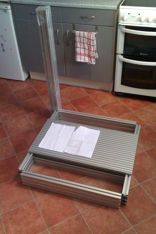
Then on to a mock assembly to make sure it looks ok:
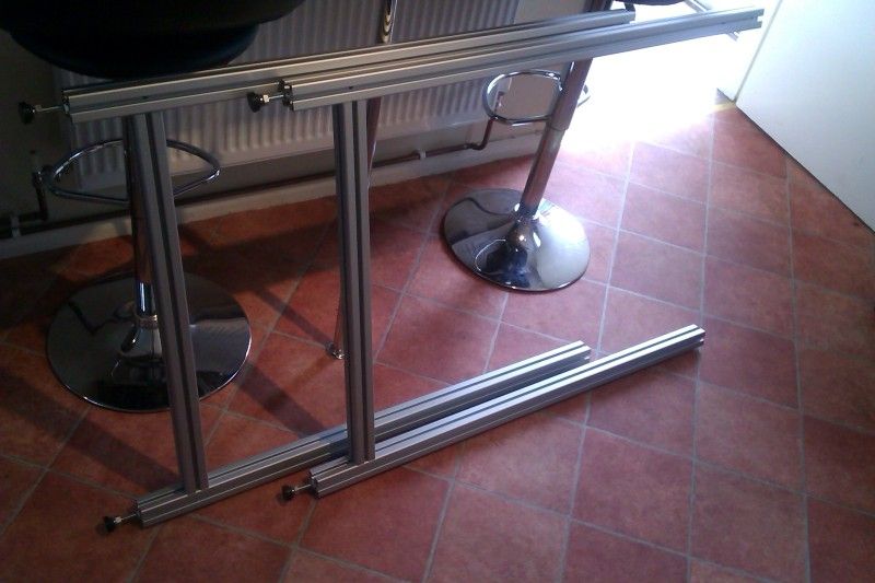
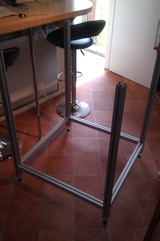
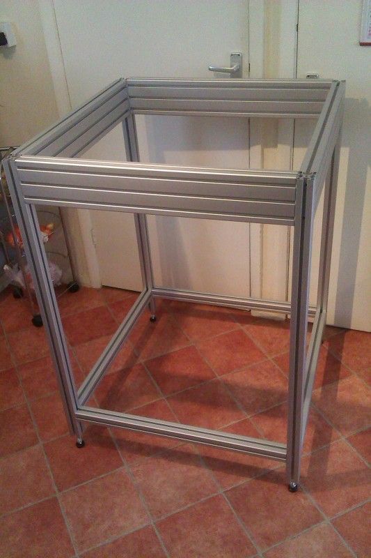
Perfect, a solid accurate level frame with enough room underneath the table for housing the control, pc, drives, tooling etc. Finally I laid the aluminium extrusion profile Im using for the machine table on top:
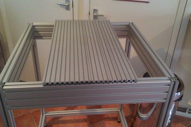
Next up is to finalise the design for the hardened linear rails, linear bearing guide blocks, ball screws and stepper motors; that said I can then cut this profile to suit, and make the carriage for the x axis as shown atop the sketch:
Sit down time with a good bottle of ale:

Hopefully when its complete Ill be able to mill 2D images to 3D, and produce high precision parts.
Thanks.
-
25-08-2012 #3
 Last Activity: 27-04-2020

Wouldn't the frame be stiffer with a few diagonal members added?
-
26-08-2012 #4
Last Activity: 13-10-2013
 Originally Posted by boldford

No, you must be unfamiliar with my materials, the stuff im using is stiff and strong enough for what i need it for.
//EDIT - (Two months later to the day) Oh how wrong and misguided i was, keep reading and you'll see progress from this day forth hehe.Last edited by Hobgoblin; 26-10-2012 at 08:18 PM.
-
26-08-2012 #5
 Last Activity: 19-01-2024
 Think you'll find he's correct and Yes I am familiar with your materials.!! Originally Posted by Hobgoblin
What your not accounting for is the Mass of the gantry and it's inertia.?
It doesn't so much matter what your cutting the Mass of the gantry will have a big affect and actually if soft material then usually means high feed rates which affectively makes the gantry a very heavy thing indeed which will put more stress upon the frame trying to twist it and push it out of shape.!! . . . At this height and narrow width and also from the look of your doodle showing the high gantry sides I wouldn't be one bit surprised if it didn't try to tip it over when rapiding at even mild speeds.? . . . I would certainly think about bolting it down or have plenty of ballast low down.!!
For the little extra cost it would be well worth it to brace the frame now rather than find out it's twisting and moving around while cutting then have to do it later and go thru all the shimming and setting up again.!!
-
The Following User Says Thank You to JAZZCNC For This Useful Post:
-
26-08-2012 #6
 Last Activity: 05-04-2020
What sort of accuracy are you expecting and how do you propose to get zero backlash, or is that meant to read 'near enough zero'? Originally Posted by Hobgoblin
Last Activity: 05-04-2020
What sort of accuracy are you expecting and how do you propose to get zero backlash, or is that meant to read 'near enough zero'? Originally Posted by Hobgoblin
How wide is the machine, about 600mm between the bearings? It appears from your initial sketch that you are only using one ballscrew to move the gantry which I'm confident you will regret since you describe this as a CNC Mill, not router, implying you wish to use it to cut metals.
Originally Posted by boldford
Yes, it would be significantly stronger. If the frame is stiff enough without (which it's not) then that just means smaller extrusion could have been used with diagonal pieces for the same strength but lower cost. Still, they can be added at a later date.
-
27-08-2012 #7
Last Activity: 07-10-2018
I agree with the guys on this one. That frame is going to move. As Jazz says given the height of the frame this will probably need fixing down.
-
27-08-2012 #8
Last Activity: 13-10-2013
Just to clear a few things up.
I do welcome the feedback and criticism good or bad as it helps to keep in mind the planning and checking process.
The purpose of this project for me is, first of all just to be able to, and then for as said engraving, hard woods, plastics (acrylic lexan etc) and possibly aluminium. This isn’t unachievable with this setup, however trying to skim a cylinder head or reproducing engine parts is.
Achieving a level table, parallel axis and zero backlash can be achieved with the right setting equipment, depth micrometers height vernier's DTI's (which I can borrow freely as I do this stuff for a living but on a much greater scale), as for backlash if any is present when finished this can be compensated for in the software I intent to use to control the machine.
Vibration and tool chatter will be a problem in certain situations and of course it won’t be as easy to overcome as removing some of the inserts from a cutter to stop such resonating because this isn’t a large machine with a large face milling cutter.
But I can only try to design what I can afford for the intended purpose and strengthen it where possible. Reducing depth of cut, feed per tooth per rev, spindle RPM tweaking all the basic parameters if in a situation where I’m still getting chatter/vibration.
I was actually quite impressed by the overall mass of just the base once it was assembled and it certainly isn’t flimsy stuff even the 20x80 is very strong.
I have considered making some brackets coming off the bottom corners of the frame that, once the machine is levelled at the base, will also bolt into the ground.
In the final stages of designing the next steps at the moment, all the planning for the traversing carriage, the guide rails, ball screws, stepper motors, and brackets needs to be carefully considered so that I don’t encounter any parts fouling on others.
The machining area should be about 400x500x150mm when complete but thus depends on how things develop; there will defiantly be room for A3 though.
Thanks.
-
27-08-2012 #9
 Last Activity: 23-09-2017
Backlash compensation in software is a fudge at best. Originally Posted by Hobgoblin
Last Activity: 23-09-2017
Backlash compensation in software is a fudge at best. Originally Posted by Hobgoblin
When a cutter is doing a circle, at the 4 quadrant points the tool is free to move and will grab in the climb milling direction whilst the software is working out which way to go.John S -
-
27-08-2012 #10
Last Activity: 19-01-2024
Thats great because I'm sure were going to give get plenty before your done. . Originally Posted by Hobgoblin

I hear what your saying regards usage but still that Gantry has Mass which will try to bend and twist the frame. Even when engraving or V-carving etc the small and sharp direction changes will rock,twist and resonate the frame which all transfer back to the job.! . . . Extra bracing will help with this is what where saying.!!
Re-Backlash then it ain't easy getting true zero and software comp isn't a very good answer or backup IMO but that said the Chinese ballscrews will be more than good enough for this machine and it would be pointless going to all the trouble of trying to achieve true zero has it requires a much stronger base frame than what this design provides.
Keep up the good work and pics coming.!
-
The Following User Says Thank You to JAZZCNC For This Useful Post:

 Reply With Quote
Thread Information
Users Browsing this Thread
There are currently 1 users browsing this thread. (0 members and 1 guests)
Similar Threads
-
Emco mill 50 Y axis travel?
By gavztheouch in forum Emco Milling MachinesReplies: 0Last Post: 01-03-2014, 11:10 AM -
WANTED: 3-Axis Mill recommendations
By TomB in forum Items WantedReplies: 0Last Post: 05-10-2012, 10:06 AM -
NEW MEMBER: Goal - Enable 3-Axis CNC Bed Mill to Perform 5-Axis Milling
By LoveLearn in forum New Member IntroductionsReplies: 2Last Post: 25-01-2012, 08:46 PM -
FOR SALE: Mini Mill Z-Axis stuff
By pjm in forum Items For SaleReplies: 0Last Post: 17-06-2010, 10:00 PM

Bookmarks