
Thread: Scrap Heap Challenge
-
09-09-2012 #11

 TrickyCNC
Last Activity:
TrickyCNC
Last Activity:


Using a CNC to make money, doesn't have to be all pretty carvings ! Here, mine is cutting mortices in table legs .. (yes, I had the phone the wrong way up ! ) CLICK TO PLAY
-
11-09-2012 #12
TrickyCNC
Last Activity:
a paste from my build thread on another site ...
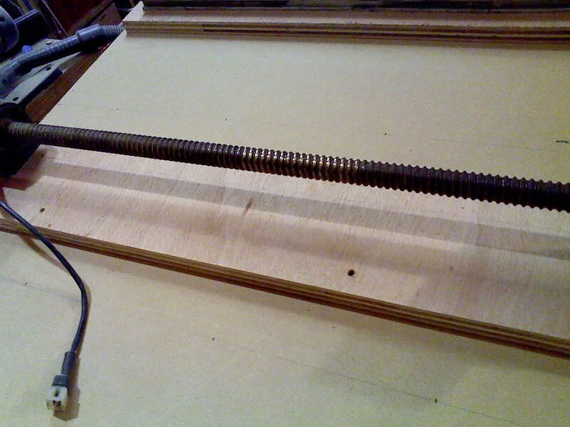
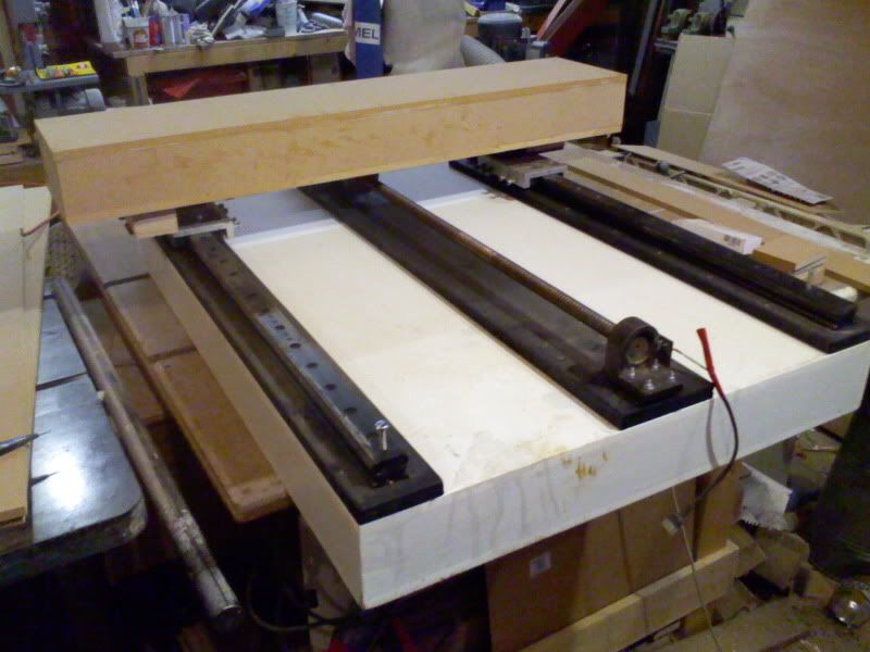
the basic layout of the bed and X axis....
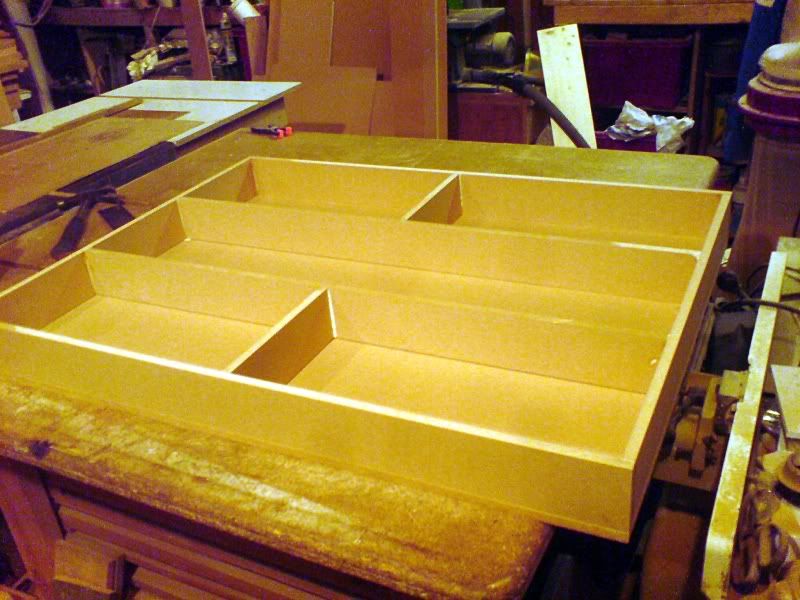
I've made the bed in the form of a torsion box out of 1/2" MDF.
Finished bed size is 36" x 27" x 4" - max working area will be about 26" x 26"
I've laid the screw and rails on top roughly in the position they will be in, except it will be the bottom when finished.
The gantry will be torsion box sections too , and fixed to the rails under the bed for a clean look.
The bed will be raised on legs when I figure out how high they need to be !
.......
,........................
.................
anyhoo,, today I spent a couple of hours on my build.
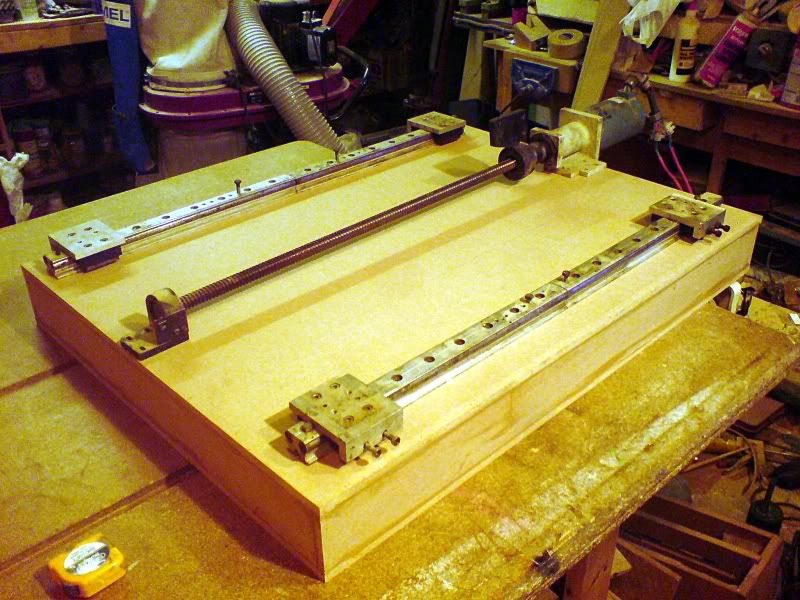
the rails I lined up on a bit of 3/4 ply, using a new ground level as a straight edge.
I drilled through and counter bored underneath, before grinding off the bolts before tightening
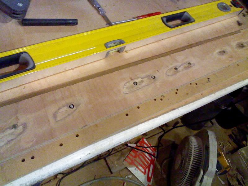
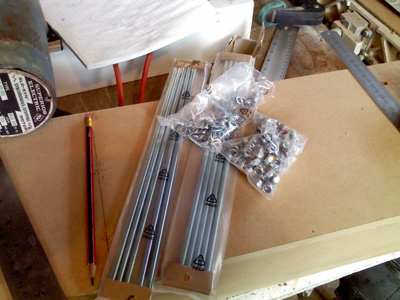
I must say, the mixed sets of machine screws / washers / nuts etc . are one of the most usefull buys I ever bought !
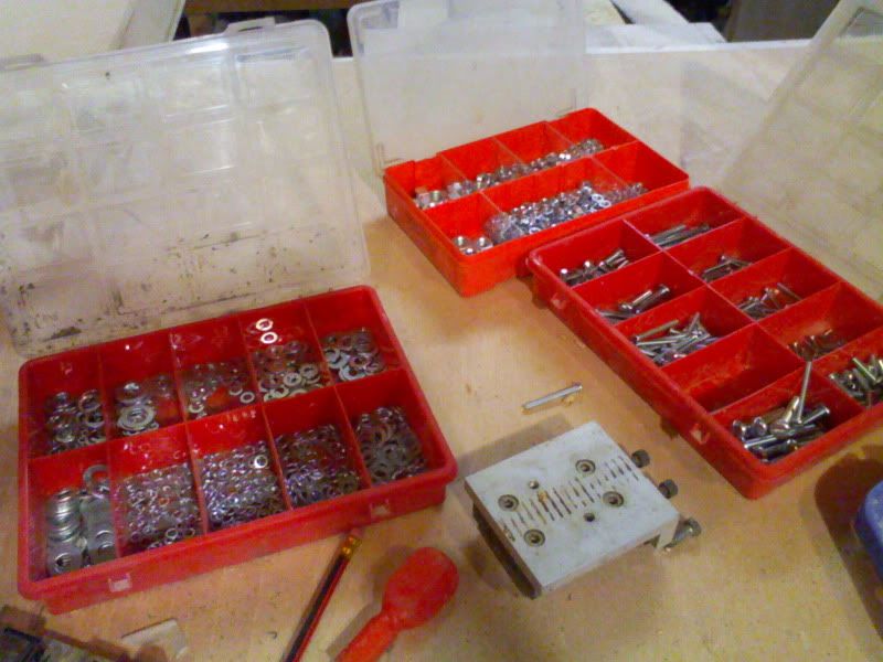
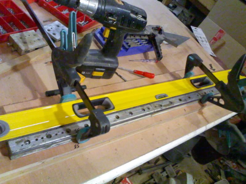
I mounted the motor / screw assy on a bit of ply and shimmed it to be parallel
and this is them all layed out .
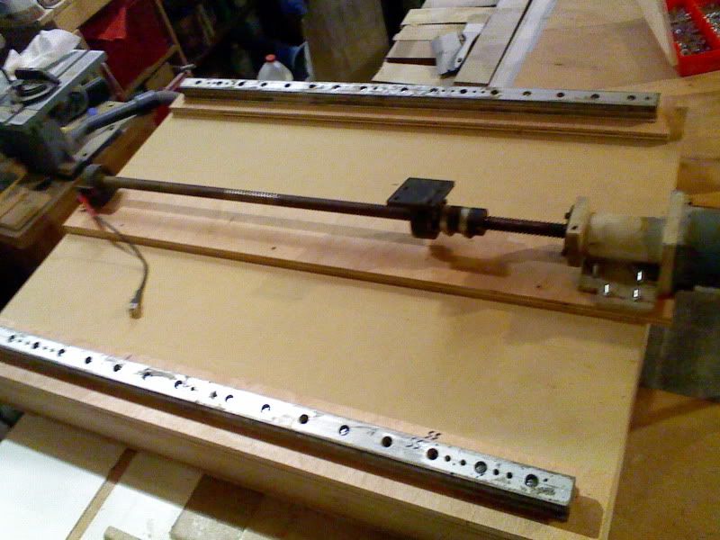
I now have to fix one to the bed and set the others in place of the 1st fixed bit.
I'm deciding whether to use the screw as the ref , or a rail .. but I don't suppose it matters much.
-
11-09-2012 #13
TrickyCNC
Last Activity:
So, I fixed the screw in the center line under the bed.
Then I fixed one end of each rail.
I then fixed a temp gantry to tie the 3 together, and ran the screw to the other end of the bed.
Then fixed the far en of the rails.
Then ran the gantry back a couple of inches at a time and fixed the rails as I went.
Quick phone vid of the X moving... remember , this is upside down at the mo.
CLICK IMAGE TO VIEW
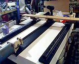
I got it upto about 100IPM before it stalled, but I'm still running the drivers at minimum amps whilst testing. It's running at about 70IPM in the vid
Rich[/QUOTE]
-
11-09-2012 #14
TrickyCNC
Last Activity:
Starting the gantry ..........
nothing impressive done
made a bracket from 1/4 plate for one of the bearings as I only had 3 out of 4.
Made the top and bottom gantry torsion boxes
Got to paint a dolls house tomorrow, so prob wont get much done here
Rich
........................
]got the under gantry mounted. Just bolted at the moment. If it moves at all, I'll glue it.
I added some temporary legs and got it right side up.
Played about with the settings, and upped the amps on the driver, got it upto 168IPM, with the acceleration almost instant
It moves pretty strong too, I can put a lot of force against the direction of movement and it keeps going.
I'm very happy so far.
it's moving about 20" back and forth in this video clip
<embed width="600" height="361" type="application/x-shockwave-flash" allowFullscreen="true" allowNetworking="all" wmode="transparent" src="http://static.photobucket.com/player.swf" flashvars="file=http%3A%2F%2Fvid121.photobucket.co m%2Falbums%2Fo238%2FRichAAC-UK%2FMOV00004.mp4">
-
11-09-2012 #15
TrickyCNC
Last Activity:
I made the gantry bridge tonight.
the top and bottom are 8 x 4, the uprights are then 9 x 3 .
It's just glued and pinned, so I'll have to wait till the morning to see how stiff it is, but being a bit gentle with it tonight I'm quite impressed !
I also like the video my el cheapo phone can produce ... perfect for this kind of thing !
so, some more :)
<embed width="600" height="361" type="application/x-shockwave-flash" allowFullscreen="true" allowNetworking="all" wmode="transparent" src="http://static.photobucket.com/player.swf" flashvars="file=http%3A%2F%2Fvid121.photobucket.co m%2Falbums%2Fo238%2FRichAAC-UK%2FMOV00005.mp4">
-
11-09-2012 #16
TrickyCNC
Last Activity:
I'll fix the video links so they work in this forum when I get a chance :)
-
11-09-2012 #17
TrickyCNC
Last Activity:
Starting the Y movement parts..................
so, I very quickly realised that the clearance will be reduces when the Z assy goes in ! oh well, I'll try and design it to be as thin as poss under the Y.
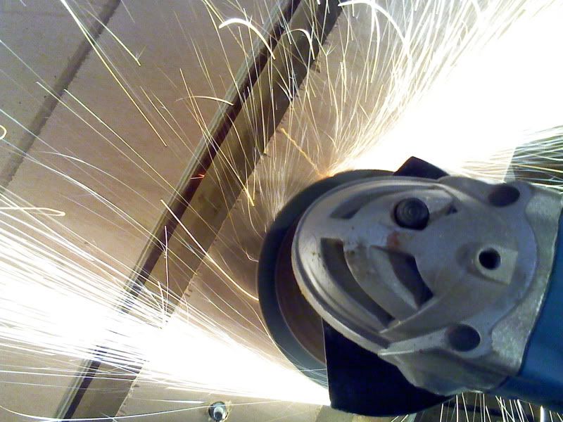
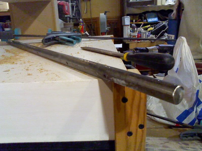
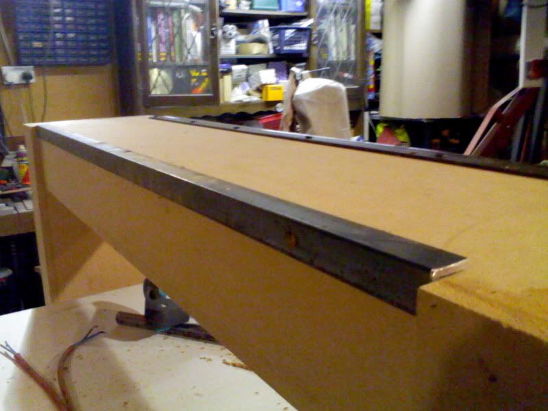
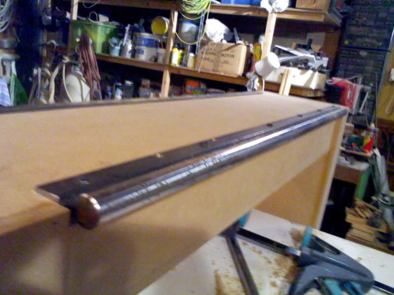
I had some precision supported rail (without the support ) from the skip (dumpster) stuff.
I cut it in half with an angle grinder, and made some supports from angle iron I have knocking about.
That's about it for today. I bought some M8 threaded rod / bolts / nuts / and washers, so will start on the bearing trucks tomorrow
 [/QUOTE]
......................
-
11-09-2012 #18
TrickyCNC
Last Activity:
.............................
So, not much done today to show.
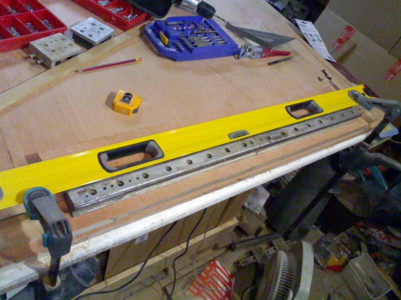
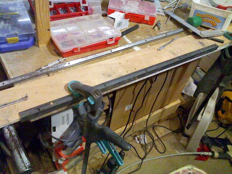
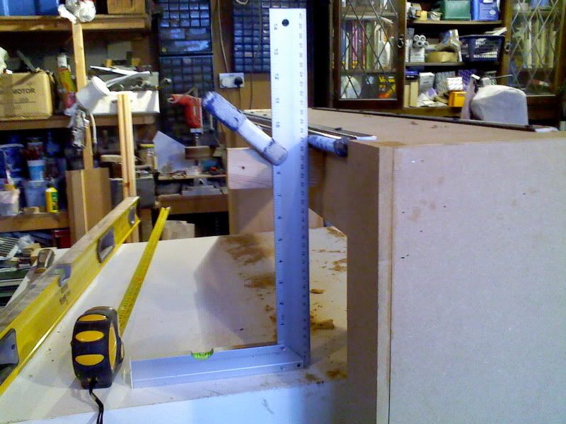
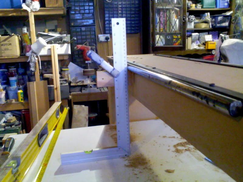
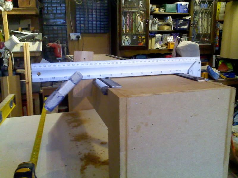
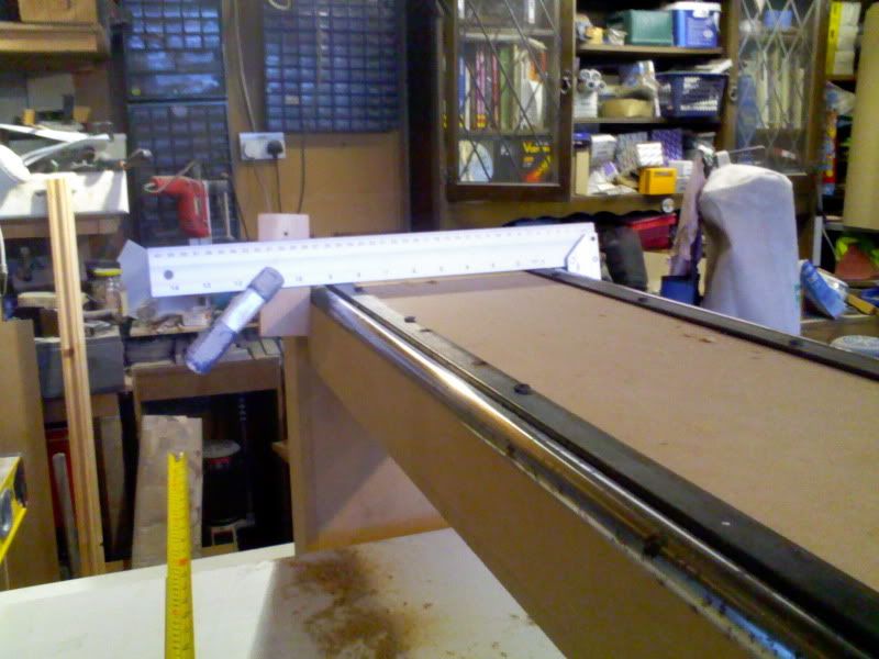
I got the Y rails more or less aligned (good enough for now)
Simple setup with a set square and clamp, 1st I got the height from the bed equal along the length of each rail, and both rails equal to each other.
Then I checked the distance from the outer edge rail to rial along the length.
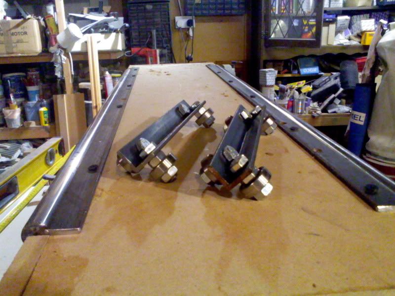
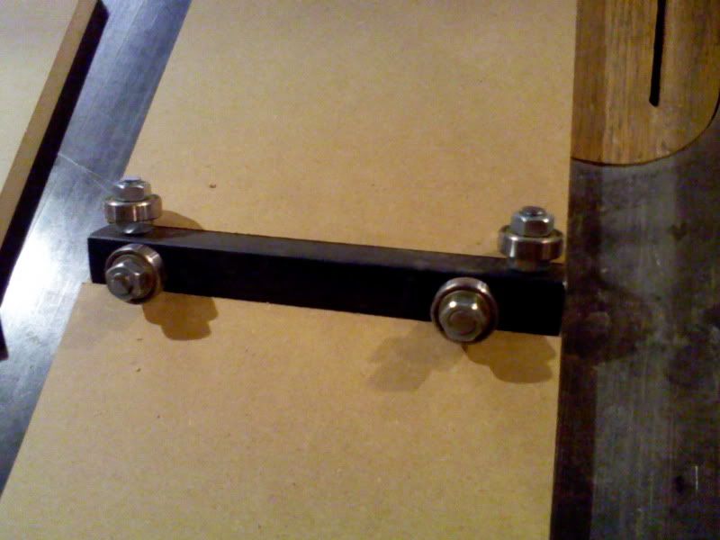
then I got to making some skate bearing trucks.
the rails are 31" long, my travel will be about 25" long, so I cut some angle iron to 7" and drilled the holes 1/2" in for the bolts for the skate bearings. spaced with nuts, and cut to length after with the angle grinder.
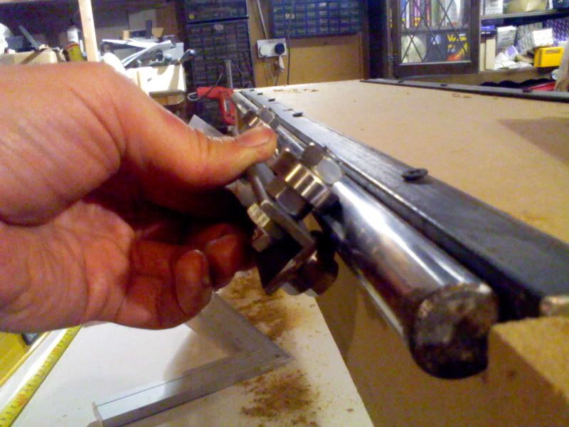
next to figure the best way to atatch the trucks to the Z carriage ???
I'll be asking that in another thread :)
-
11-09-2012 #19
TrickyCNC
Last Activity:
so, today I had to clear the CNC project to one side to do some paid work
I cut this stack of MDF to make 2 house shaped bookcases, which is the kind of thing I make most of my living off
This is the stack
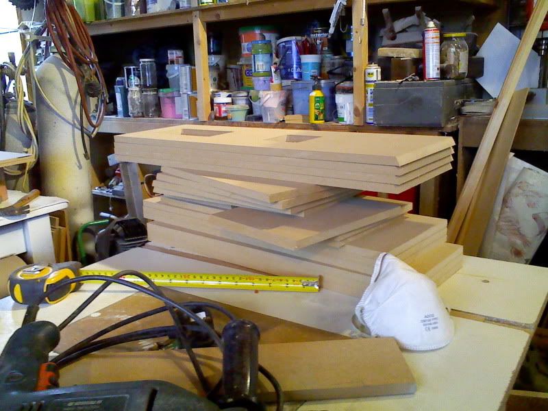
it's one of the things I want to cut by CNC
the finished item looks like this
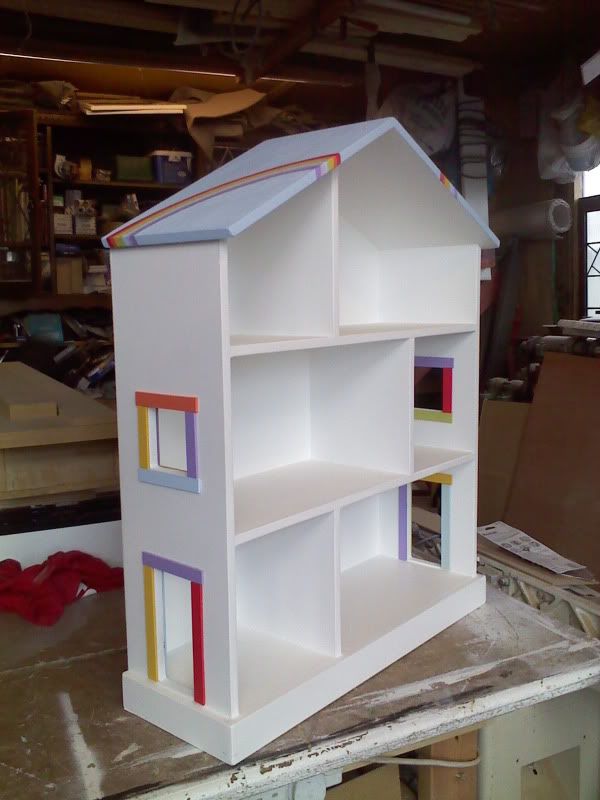
this one was ordered with rainbows for a children's therapy room.
anyway, I'll assemble them tomorrow.
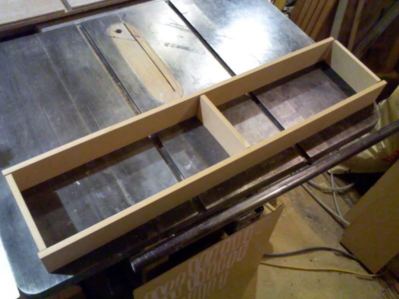
I got the Y carriage mostly built later today
I dado'd out for the bearing trucks, based on Ger's answer to my other post. Thanks Ger
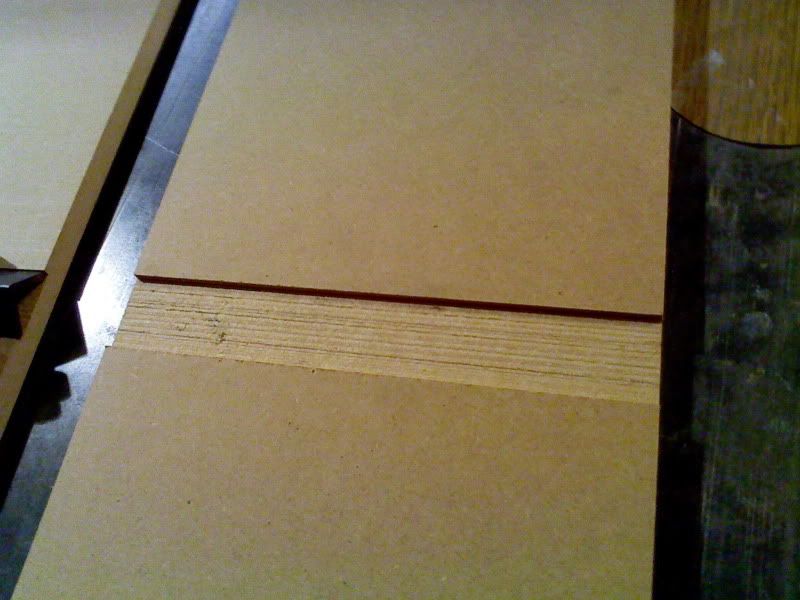
The bolt head were a little proud, so I ground them on the belt sander
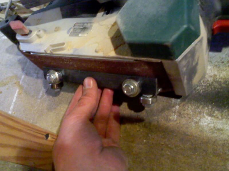
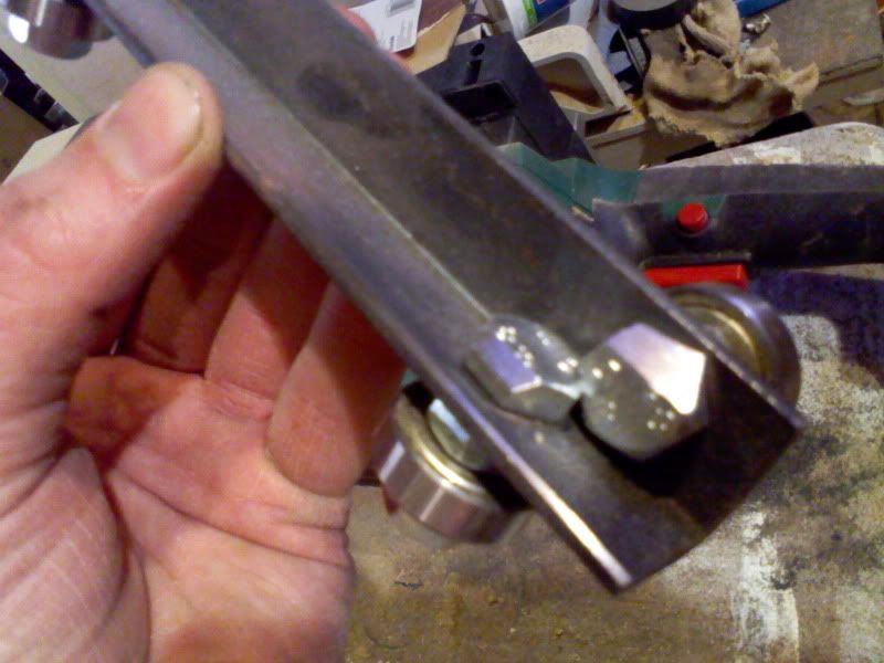
for a nice fit
I made a torsion box at the top, and a removable bottom plate for dissassembly.
A threaded rod just above the bearings for the pre load adjustment
I might make a fitted side plate if it needs stiffening (to stop nodding), will know more tomorrow when the glue has dried
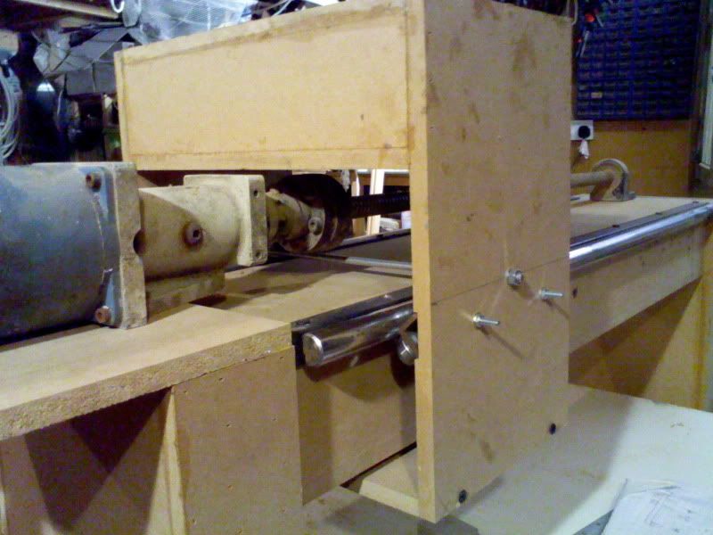
it rolls pretty well
<embed width="600" height="361" type="application/x-shockwave-flash" allowFullscreen="true" allowNetworking="all" wmode="transparent" src="http://static.photobucket.com/player.swf" flashvars="file=http%3A%2F%2Fvid121.photobucket.co m%2Falbums%2Fo238%2FRichAAC-UK%2FMOV00009.mp4">
I'll connect the screw assy tomorrow, then to start on the Z
I hope to make some sort of 1st cut by the end of this week :wee:
-
11-09-2012 #20
TrickyCNC
Last Activity:
]Spent today beefing up the carriage.
I filled in the sides, and added a mini torsion skin the the front. I'll do that back at a later date. Lined up for the screw to be bolted up.
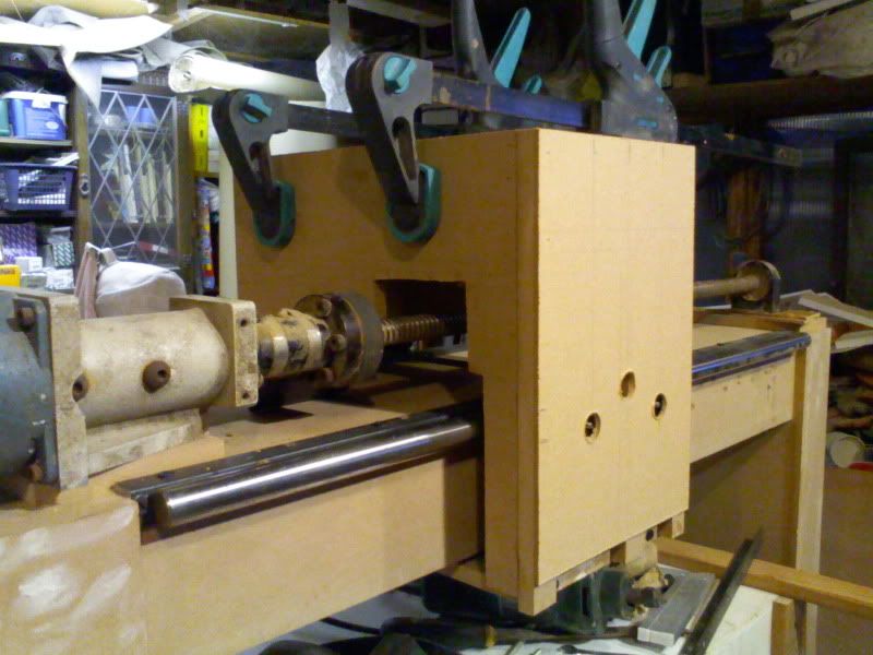
Now it's just the Z to make and I can test it :D
so, tonight, I'll mostly be looking at everyones Z's and choosing how to do mine.[/

 Reply With Quote
Thread Information
Users Browsing this Thread
There are currently 1 users browsing this thread. (0 members and 1 guests)
Similar Threads
-
Recycle electronics or scrap?
By gavztheouch in forum General ElectronicsReplies: 2Last Post: 05-02-2014, 04:16 PM -
BUILD LOG: Definately a scrapyard challenge
By motoxy in forum DIY Router Build LogsReplies: 158Last Post: 29-10-2012, 10:12 PM -
NEW MEMBER: Up for a challenge......
By swatt in forum New Member IntroductionsReplies: 1Last Post: 03-10-2010, 10:57 PM -
Fancy a challenge?
By cassius in forum Machine DiscussionReplies: 5Last Post: 03-09-2010, 02:44 PM -
BUILD LOG: Work scrap bin router build
By Vic66 in forum DIY Router Build LogsReplies: 32Last Post: 17-01-2010, 08:51 PM

Bookmarks