
-
27-02-2013 #1

 Last Activity: 10-12-2021


Hello all,
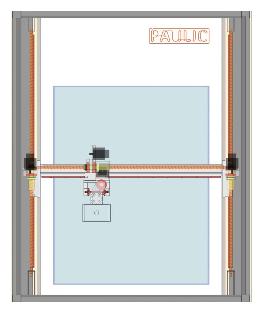
I want to have for my first build an all rounder, to be able to use it for large sheets or small wooden, plastic or aluminium jobs as well as big light foam. So I ended up with a design without a raised gantry, and everything independent from the table. I dont have the table design yet. Maybe I will have one side of the machine fixed to the wall. I plan to have a table for max. 10-15 cm thickness and one close to the floor for big foam works. In the future I plan to add a rotary axis and/or B/C head.
I will have a maximum travel of: X axis 1350mm; Y axis 1070mm and Z axis 650mm. I estimated the gantry weight without spindle at about 85kg and I think thats heavy and a problem for me. I dont have now the money for 7A drives but only for the DIY drives based on the THB6064AH chip (4.5A 50VDC) and I want to get some 4A, low inductance, 3-4Nm, nema34 steppers (to be upgraded) and will see if and at what speed I will have my gantry moving.
It was easier for me to draw the plans in 2D and I hope you will understand them.
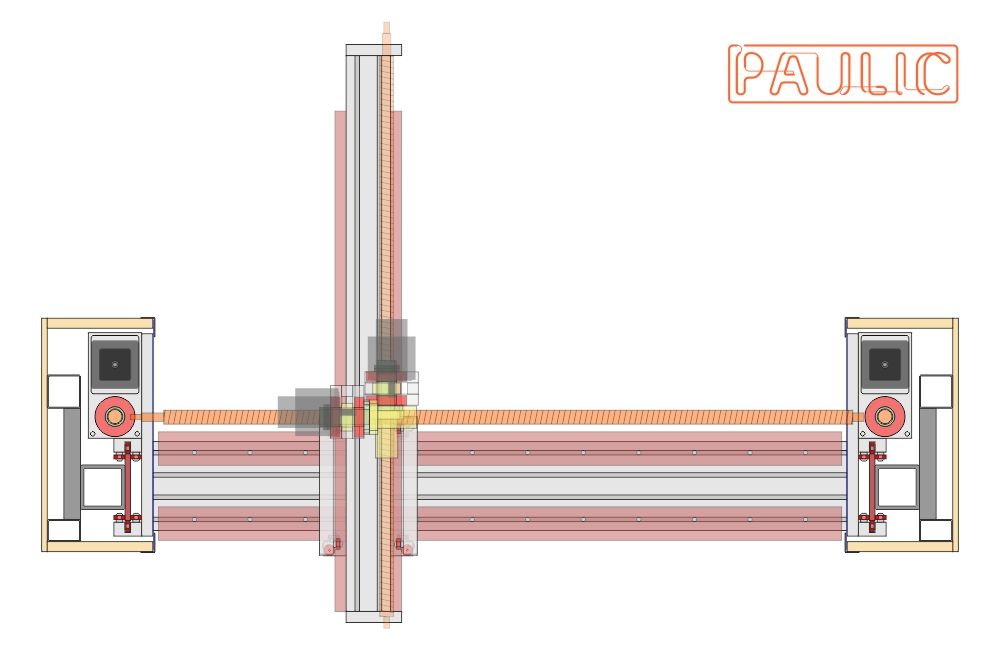
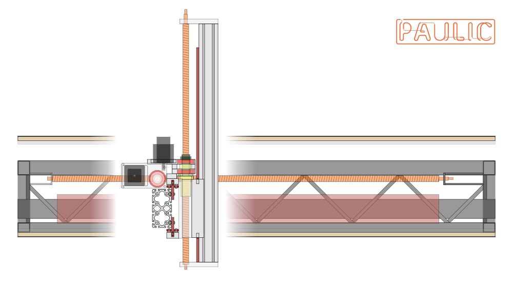
Some details: the main frame (dark grey) is made of welded rectangular steel tubes; the linear guides (dark red) are CNCRouterParts style but thicker (120x10 and 60x10), harder and precision ground; for the gantry 160x80 heavy aluminium extrusion (1.25m) and for Z axis 80x80 (1m) and I want to have enclosures for all axes to protect the screws and rails from dust.
I want to ask Jonathan and others who use the rotating ball nuts what screw diameter and thread recommend. I would have been happy with the 20mm diam. and 10mm pitch but Chai has only 1605, 1610, 2005, 2505 and 2510. I think that 2005 is the best choice for Z but for X (1.6m) and Y (1.25m) will I be safe with the 1610 or I should go with 2510? If I go with the thicker Ill need larger pulleys and longer timing belts which I dont like.
Cheers,
Paul
-
27-02-2013 #2
Last Activity: 10-12-2021
Here is my last version drawing of the rotating ball nuts based on Jonathans design. They have two pairs of timing belt pulleys so I can easily change between 2:1 and 1:2 ratios.
I tried to make the design as compact as possible to allow me to have the screws closer to the gantry/rails and consequently the spindle as close as possible to the gantry rails.
The three drawings are for 1610, 2510 and 2005 ball screws. Still not sure which ones to use.

Last edited by paulus.v; 27-02-2013 at 04:30 PM.
-
02-03-2013 #3
Last Activity: 10-12-2021
Nobody says anything... There must be something really wrong with my project.

-
02-03-2013 #4

 Last Activity: 05-04-2020


Normally I'd say make the Z-axis as short as possible, but if you really want a B/C axis head then you do need a long Z-axis. What drive mechanism are you planning on using for the B/C axes? Either way the gantry needs to be *much* stronger. Look at some of the past build logs on this forum to get ideas.
You should run the motors on about 70V - drivers are around £35 each from China, which will be far superior to the TB6xxx ones.
Z is fine with RM1605, Y is best with RM1610. No point using a rotating nut on Y or Z as it's not near the critical speed of the screw.
With X you're on the borderline for using RM1610. If your maximum travel is 1350mm, then you should be able to use a 1450mm screw quite comfortably which would be fine with RM1610 without the rotating nut. If you want it to be a bit longer, then the rotating nut with RM1610 will work very well. Putting both pulleys on to get 2:1 and 1:2 is a nice idea, the problem is it doubles (ish) the moment of inertia, which will greatly affect the acceleration you get. For that reason I would stick with just the one pulley and make the shaft as short/lightweight as you can.
-
The Following User Says Thank You to Jonathan For This Useful Post:
-
02-03-2013 #5
 Last Activity: 06-07-2022

Hi Paulus.
ive been reading your posts :D
Im no pro though so bit reluctant to say anything. But as nobody else has Il tell you what I think
Everybody who joins here, including me. Says, "I want a machine that can do everything!. Foam through to ali"
You can cut ali with a blunt spoon.Problem is it will take ages and it wont look very good when youve finished. As youve mentioned jonathons machine above youve obviously read his thread. Im sure he will agree with me by saying his machine is designed to cut ali therefore wouldnt do the best job of cutting foam? hope im not treading on toes saying that!
From what Ive learnt (see above comment im no pro!) is that your much better to pick a target material and make the machine cut that. For example If you plan to cut ali. The machine needs to be absolutely rigid in which case I suspect your Y/Z design holds the spindle too far away from the Y axis.
ALso, cutting ali doesnt require speed.
MDF (not sure if they call it that in the states?) requires faster movement to avoid burning. same with acrylic.
What im getting at is, your much better trying to focus on one material. design for that and its a lot easier for people to make comment on your design at present perhaps nobody is saying anything because what your trying to achieve will simply not work (very well)
Although credit is due for spending the time to do these drawings, il be honest, i cant visualize it very well and this may also have a bearing on others not saying much.
Read reviews on those drivers before you buy
download google sketchup, 'think its called Trimble' nowadays. Its free, its 3d warehouse or whatever gives you all the components (linear rails ballscrews etc) and perhaps with a 3d design you may get some bites from the bigger fish.
Keep posting.. beauty of the internet is even though you think your talking to yourself, your not!
whilst typing this... you've had a bite!Last edited by kingcreaky; 02-03-2013 at 11:38 PM.
-
03-03-2013 #6
 Last Activity: 01-11-2013
Ditto..... And to add to the defence's case in mitigation .....
Last Activity: 01-11-2013
Ditto..... And to add to the defence's case in mitigation ..... Originally Posted by kingcreaky


+ This forum is often quiet over weekends
+ Some of us are too inexperienced to offer advice
+ It's mostly only Jonathan who has specific experience of the rotating ballnut design?
Seriously though Paulus, whilst you have have obviously put a great deal of effort into your drawings, I think some of our minds have been spolit and brainwashed with 3D!
Your design looks good to this newbie.... Keep posting....
AndyLast edited by WandrinAndy; 03-03-2013 at 07:21 PM.
-
05-03-2013 #7
Last Activity: 10-12-2021
Thank you all for the replies,
I will try to build something like this. My concerns are about the gantry twisting from the long distance between Y rails and spindle. But if/when I will upgrade to servos I will be able to add more weight to the gantry and double/triple the profile/stiffness. Originally Posted by Jonathan
Yes I know. With 7A/80V Ill get easy 600-800 IPM but this will be for the future upgrade. I cannot find on ebay any 70V drives at £35. Anyway Ill enjoy soldering the components to build my drives :) Originally Posted by Jonathan
I chose RM2005 for my long Z axis (20kg+spindle) to have a smaller thread angle and the rotating ball nut to avoid the motor weight added up to moving Z part. Do you think RM1605 will be fine? I do not want the spindle to fall when I turn off the power. It will be easier to make all the rotating nuts the same size. For Y I will consider rotating the screw but not sure if the RM1610 or RM2510 and for Z definitely RM1610 with rotating nut. Originally Posted by Jonathan
I completely missed to consider the moment of inertia of the rotating nut assembly. Never thought it could be greater than the 1.25m steel screw. But after calculations it is actually three times greater with both pair of pulleys and equal to the gantry inertia, (0.75 vs. 2.3 kgcm2). I can reduce it at least to half by profiling or drilling the pulleys. Thanks again for enlightening me about this important aspect. Originally Posted by Jonathan
Yes I wasnt clear in my description. I want to be able to cut ali only occasionally. Maybe better not to mention ali at all. The main materials will be wood up to about 10-15cm thick and foam up to 65cm. This is why Im trying now to design a removable/adjustable table to be able to put the hard material as close to the gantry as possible. Originally Posted by kingcreaky
Ill make a simple 3D model if I have the time but I will rely on my accurate drawing for all the dimensions I need. I work better in 2D :) Originally Posted by WandrinAndy

 Reply With Quote
Thread Information
Users Browsing this Thread
There are currently 1 users browsing this thread. (0 members and 1 guests)
Similar Threads
-
LIMAC knife cutting machine and plasma machine, cnc router latest video
By therouterlady in forum Manufacturer NewsReplies: 0Last Post: 18-09-2013, 05:28 AM -
My first 700 x 500 x 300 Mill/Router machine
By Lovre in forum Gantry/Router Machines & BuildingReplies: 16Last Post: 09-02-2013, 09:28 PM -
Dm 6090 cnc router machine from china
By troyboy1 in forum Milling Machines, Builds & ConversionsReplies: 1Last Post: 04-12-2012, 11:19 PM -
Need help setting up a CNC router machine please
By 1albobs in forum Gantry/Router Machines & BuildingReplies: 4Last Post: 27-02-2012, 06:16 PM -
CNC Router Machine?????
By anamsey in forum General DiscussionReplies: 1Last Post: 09-07-2011, 08:01 AM

Bookmarks