
-
18-06-2014 #101

 Last Activity: 06-06-2017


Hi,
Thanks for shearing your design and experiences is looking really good so far. I am planning to build a similar cnc router with a working area of 1100mm by 600mm and 250 on the Z. I still have to figure out how to solve the z axes as the longest bit that I need to use is 250mm by 22mm dia and has to be able to travel on top of the 250mm material block.
I have noticed earlier that you had some issues with temperature changes which has me a bit worried as I need to build the machine at normal temperature but it will have to work at -5 degrees Celsius. Common sense tells me that since it will be in there all the time everything will shrink at the same time so hopefully I should not have problems.
Could you please tell me how much this project cost you so far everything included.
Thanks again for shearing.
-
24-06-2014 #102

 Last Activity: 15-04-2024


 Originally Posted by HipoPapi

Sorry have been busy. I have all mounted and finishing electronics and cables.
-So it seems there will be no problem following the design and making 250-300mm Z. Most wisely it seems is to make the sides of the construction deeper, by making the stairs like profiles a bit longer and the Z, keeping everything else same.
-2700-3200eur in materials, depends on how you deal with customs. using quality cables and so.
Now i before i update with pictures and details i have a question. Please sb. help cause my ignorance here is astonishing! I thought all was simple and obvious, but...
I have a toroidal transformer 2x50VAC and Power Regulator Board PSU. So one side of the board says AC1 AC2 AC3 AC4. Here i connect AC1, AC2 to the 50VAC1 and AC3,AC4 to the 50VAC 2.
At the other side it says VDC+ VDC+ Ground Ground Ground VDC- VDC-, so as i need 70VDC i connected Both VDC+ together for the + and both VDC- together for the -, but now i gave 140VDC measured between + and -. What i am missing??? i remember the time at school when + was + and -was-, something changed these years or what?
PS: PSU problem resolved, Neale helped me here http://www.mycncuk.com/threads/7659-...9481#post59481Last edited by Boyan Silyavski; 25-06-2014 at 11:44 AM.
-
27-06-2014 #103
Last Activity: 06-06-2017
Thanks Silyavski for your reply and I am glad you sorted out the psu problem.
Have you managed to assemble the Z axes and could we have some pictures please.
-
27-06-2014 #104
Last Activity: 15-04-2024
Hi,
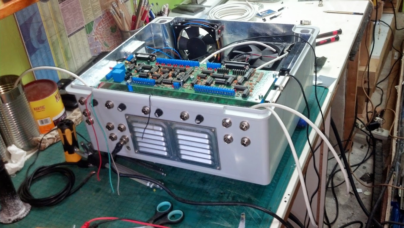
just finished almost everything from the machine part and cables. The box its almost ready.
First of all-Thanks for the interest you are taking in my build!!! And the help of course.
Here are some photos:
/sorry they can be big on small monitor but seems they can not be parsed from G+ so had to copy paste them./
1. The Z axis. 2x6mm plates bolted together. At the back side/not seen/ 2x 20x16mm solid steel bars, on top of them at the back are mounted the rais. 16mm is the distance needed to bolt exactly the ball nut housing.
Generally speaking is good before the build starts to buy 1000 allen bolts with cylindrical head M5x40, for example + say 100 M6x60. Hundreds go for mounting the rails, the others i cut and fit where possible. I mean buying every time 10 screws from the shop is expensive. All bolts together on the machine could easily cost 150euro or more. At local shop the 1000 M5 bolts sell for 60 euro. I found them for 15 euro after extensive online search. The magic word is Din 912
-The M6 bolts are for fixing the screw mounts, ball screw bearings at both ends, linear bearing carriages/hiwin 20/. Where needed i cut them to size. hell i cut a lot of screws these weeks.
- The spindle mount brackets are cast, means not perfect. So i had to fix them on place , mark them, measure, then drill .
2.View from side . My dog is again bored from my craziness.
I am still not convinced how i have to wire the proximity switches. I mean as Limits or Limit + Home. The cables i use is 8 pin. I am still not convinced at that squaring the gantry thing.
Lets see- the machine is perfectly square. And when i say perfectly look at this - moving one of the long ball screws that move the gantry, the gantry moves with ease and the other ball screw rotates by itself :-), all along the distance i mean. I tried moving them in opposite directions but there is no play so actually i can not make it not square, at least by hand i mean.
For the moment i will go as so far that connect the gantry switches only from the left side and make all limits. It will save me some thinking how to pass the cable from the right side. Will do some tests and see if its worth connecting them Limits and Home. For the purpose will make a small connection box at the back of the Z. cause the design is so, that all cables meet there.
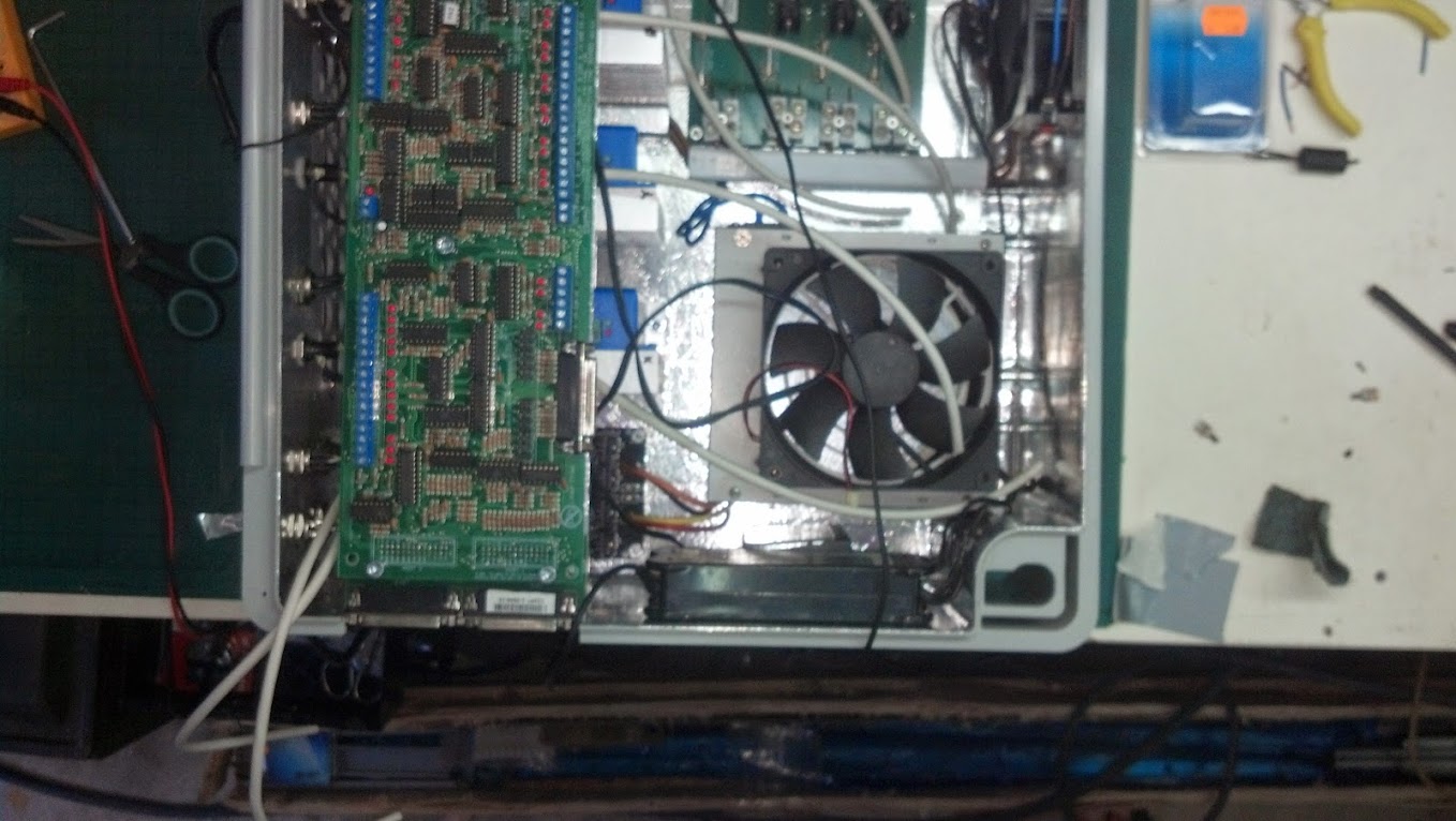
3.The box
Now this is where i wasted a lot of time. My friend just dropped me a plastic box and said -fit all here. Well, i fit it. After a lot of thinking, but was a good exercise. I made all from scratch. Next time will by a fancy box like fellow forum members do. For a reason obviously. But again, it was fun.
Let me tell you something. I wasted a whole f***ng day trying to solder with a chinese tin and flux. I even doubted for a moment that i can solder at all. So ugly and weak...
So very frustrated, i went to the shop and spend 20eur on ???g silver solder and 10 euro on flux they use for copper soldering, liquid with a brush. After a lot of thinking , yeah, i did not want to spend 30 euros more that day.
Well, what a perfect buy. A must. The flux works for everything except aluminum. The solders are Perfect. I was born again from hell. NEVER USE CHINESE SOLDER AND FLUX. Thanks to the guy on Youtube that compared the sh*t with the real thing, so i opened my eyes.
The BIG toroidal transformer /650w/ fits nicely into old PC power supply enclosure. Yes, everything is interference isolated in the box. And ventilated :-)
This is the side of the box. All connections go here. All connections realized using 4 pin and 8 pin chinese "aviation plug" . That makes me laugh. I certainly don't want to be in that plane
On my machine/next build/ i will use 4 pole Neutrik Speakon plugs only
The air comes from this side, passes through i filter/hate dust in boxes/ , cools the drives and goes out propelled by a 220v/24w ventilator at the other side.
Behind the alu plate is 4mm thick frame which gives place to fit filter. the filter is 0.7euro sheet used in kitchen filters. The box is drilled with a lot of big holes for the air to pass. Say holes total surface is 1.5x the hole of the ventilator.
The most useful instrument in making the box was STEP DRILL. I did not know what it serves for, before hand i mean , so i learned there something.
Last edited by Boyan Silyavski; 27-06-2014 at 10:21 PM.
-
The Following User Says Thank You to Boyan Silyavski For This Useful Post:
-
27-06-2014 #105
 Last Activity: 10-12-2022
Hi. The poor Dog :) Love the machine. One comment I would make is that my gantry is aluminium plate (effectively 15mm plate in box configuration) with 20mm alu side plates and I couldnt find any play from one side (X) to the other (from a racking perspective). Once the screws were connected and the motors turned, the machine was well able to rack itself. I'm actually looking forward to the independant homing of the X axis proximity switches, as Jazz noted to me before, the bullet type allow adjustment; I'm banking on this to help me get the gantry square as its being set up. Even though your machine is steel, I suspect it can rack and be adjusted.. just a little.
-
28-06-2014 #106
Last Activity: 17-05-2026
Hi, love the photos. that does look like a very substantial, purposeful piece of kit. Well done. G.
-
28-06-2014 #107
Last Activity: 11-01-2024
Would it be possible to lock one lead screw and put a dial gauge on the other side and measure how much (little) it can be moved? Originally Posted by TonyD
As Geoffrey said, a purposeful looking piece of kit - very nice :-)
-
29-06-2014 #108
 Last Activity: 19-12-2024
silyavski very good work and very helpfull thread.
I am planing a machine a little bit bigger than yours (X:1500mm Y:750mm Z:130mm real travel).
I have been inspired by your plans for my machine frame.
I have some questions about what i see.
1. How did your succed to have Z axis rails in the same plane? Did you use epoxy, or did you mill the 6mm plates?
2. Why you use 2x6mm plates instead of one plate 12mm?
3. What clamping system are you going to use?
4. What is the clearance from the lower part of z axis to the cutting surface. Also what is the real traver for your z axis.
5. Finally what is the horizontal distance ( from left to right ) for y,z axis carriages and the vertical distance ( from bottom to top) for y and z axis carriages ( outer side of carriages)?
Thanks for you time
VagelisLast edited by ba99297; 29-06-2014 at 01:09 PM.
The creative adult, is the child who survived
-
29-06-2014 #109
Last Activity: 15-04-2024
Interesting. I will do that tomorrow and report back. The gantry will not deflect for sure :-). Originally Posted by FatFreddie
The Z axis rails are in the same plane for 2 reasons: Originally Posted by ba99297
1. When i mounted the bearing blocks first, i checked the plate with straight edge. luckily it was almost straight. Some hits with big rubber mallet made it perfect.
2. Now having achieved to mount them on a plane surface, using precision square i squared 1 raw of them and tightened them. The rails were in the bearing blocks but not attached to anything else. cause when you measure long things, its easier to detect any error.Then using digital caliper i measured 150mm, tightened the bolt on the caliper and from both sides made sure the distance is the same . Tightened a bit, then with the digital caliper made sure its parallel to 0.01mm. Little bumps with small plastic hammer helped. Then tightened it finally.
I did not want to wast more time. That's what they had at hand at the metal shop. Luckily, cause they were not perfectly flat, so it took a lot of hammering to flatten them against straight edge. Originally Posted by ba99297
Its up to my friend. On my small machine i have cast aluminum grind flat plate. With a lot of tapped holes. On top of it i mount 10mm hard plastic sheet using bolts at the corners and very very thin double sided glue sheet, the ones they use in photography printing to mount photos to lexan support. I Hot melt glue all jobs. When finished, i use alcohol to un glue the detail. Originally Posted by ba99297
But with a strong and fast machine that will not always be possible. I know your doubt. I have it for my next machine and still not decided. My best bet will be to use plastic bed. I have to make some visits to the junkyard or an recycling center. And on top of it 5mm expanded PVC . However i plan to invest some money and maybe use steel channel , like a mill, but not on all the bed, just at the nearest side, so to say for fine jobs.
So that's my suggestion. Make 2 areas/ or 3 areas as i will do but my machine will be 3m long and 1.5 wide/ . One with a proper aluminum or steel bed and the other plastic.
Cause MDF will constantly need surfacing, i believe investment here will pay very fast in the future.
Vacuum i am not planning to use. The strength of vacuum is if you have production which is repeatable, or you work with sheets only. However in the future if needed you can make some removable vacuum fixtures.
Originally Posted by ba99297
260mm and real travel of 215mm
Now, careful cause this is still unconfirmed info and just a point of view. Its just what months of mind games told me. As i said it many times in the forum, cause that's my view for a DIY really multitask machine, i seem to find that the Z to bed/ frame without anything else/ 250-260mm is perfect. With the trade off that when alu sheet is routed it had to be risen another 100mm at least, using MDF, wooden or so, ribbed or solid, removable bed or fixture.
Below is how my z plate ended. As you see the solid bars combined with the rails reinforce the plate and is very doubtful it will bend, think of bending a solid steel bar ~50mm thick and at least 50mm wide, 500mm long. Another pint here is that i use 2 spindle mounts separated at spindle both ends. So the mounts and the spindle further reinforce the thing. No it will not bend in any way.
What i believe is the absolute minimum for a good strong machine- 240mm for the Z Spacing left right Originally Posted by ba99297
The vertical is my minimum for such a long Z plate. The width of 150mm is the minial as i see it , again having in mind the length
Hope that helps.
Vagelis, something else.
I have been following your build with great interest, please let me tell you something. This also to the other people that aspire to build a machine. You will need to spend at least 100eur on the following things if you don't have them, to be able to accomplish the precision mounting successfully. They are a MUST. I don't see how it can be done without them and especially by one person.
Believe me on this. Not to mention the satisfaction you will feel when all is mounted precisely.
-1m straight edge or longer.Stainless better
The Must here is to be at least long enough that it can lay on both parallel mounted rails that the gantry slides on. In other words wide as your machine. Without this you will run at the moment of mounting and later at countless problems. The best will be if it has length of the diagonal of the bed or at least of the rail.
Many will disagree but Rectangular section is better than knifed edge, especially if you work alone. Much more cheaper also.
Here is my initial experience with links from where to buy. http://www.mycncuk.com/threads/6546-...o-straight-%29
To summarize it DIN 874 is the magic word. Whatever accuracy. Or Din 866 rule, especially if you go bigger machine build. Like my next one. You guessed right, i will buy at least 2 meter one.
-2x 30cm precision squares . Din 875 is the word here. these will help solder , square the gantry, the gantry to the bed, etc. Yes, 2 of them because many times you will clamp them together in clever ways.
-1x <10cm precision square , Din 875 is the word here. Stainless betterfor the tight fits, squaring the spindle, etc.
-2x cheap chinese squares
Once you have bought a really cool reference square, you go with it to the shop and buy cheap squares to use for soldering and damaging jobs. Once you reference them against the good one.Last edited by Boyan Silyavski; 29-06-2014 at 10:59 PM.
-
30-06-2014 #110
 Last Activity: 3 Weeks Ago

Nice looking machine but the eye is drawn to those brackets from the gantry to the X ball nuts. I know from your posts that you will have made sure these are correct but I have to say they look flimsy in comparion to the rest of the machine.
You made a good job with the control box considering what you had to work with, it's been informative and a pleasure to follow your build.Last edited by EddyCurrent; 30-06-2014 at 02:18 PM.
Spelling mistakes are not intentional, I only seem to see them some time after I've posted

 Reply With Quote


Thread Information
Users Browsing this Thread
There are currently 1 users browsing this thread. (0 members and 1 guests)
Similar Threads
-
BUILD LOG: Steel frame cnc router design/build
By CraftyGeek in forum DIY Router Build LogsReplies: 110Last Post: 06-05-2015, 10:00 PM -
BUILD LOG: First steel diy CNC router build
By ivars211 in forum DIY Router Build LogsReplies: 59Last Post: 28-07-2014, 08:29 PM -
Need help, buy or build to cut steel, stainless steel, titanium etc
By fatguyslim in forum Machine DiscussionReplies: 41Last Post: 08-02-2014, 11:37 PM -
A Sturdy Steel Framed Machine Design
By Boyan Silyavski in forum Machine Frames & BedsReplies: 0Last Post: 06-11-2013, 05:58 PM -
BUILD LOG: 7' X 4' Steel frame build
By Ricardoco in forum DIY Router Build LogsReplies: 6Last Post: 28-10-2012, 06:02 PM

Bookmarks