
-
13-10-2013 #1

 Last Activity: 17-06-2020


Hi everyone,
hoping someone can suggest things to try as I'm a bit lost as to why this is happening.
I have a DM856 driver and a small Nema 23 motor, all connected to a SPS705 68VDC power supply (I was told the voltage on the PSU is a bit high for this motor, but it should run ok). This is driven via the PUL / DIR input from a custom built uC based board, which acts like a jog / test board, you press the '+ / -' buttons to turn the motor one step CW or one step CCW. If I press a button and hold it down, the pulses are generated in a cycle and the motor moves smoothly, but if I only press the button once, every now and then the motor 'clunks' or jumps a step, sometimes going reverse etc. Here's what the pulse looks like:
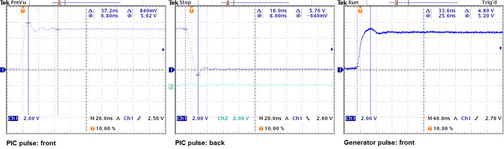
The first two (from the left) screenshots show the pulse generated by the uC / electronics, pulses are 41us wide and as per the manual the DIR signal is in front of the PUL signal (DIR is not shown here). The screenshot on the right is a pulse from a pulse generator, not much different from the micro controller generated ones. With the pulse generator the motor runs smoothly, even at 1Hz :O
Anyone got any ideas as to what might be causing the 'clunks'? the motor isn't loaded, it simply sits on a desk with nothing attached to it.
Regards,
T.
-
13-10-2013 #2
 Last Activity: 17-03-2017


Is that trace from a time when it misbehaved? How sure are you that it's not contact bounce on the switch? Where is the driver input ground tied back to? Is the driver opto-isolated and are you sure the PIC is driving it hard enough?
-
13-10-2013 #3
Last Activity: 17-06-2020
Hi Irving,
the trace shows any pulse generated by the PIC, I've looked at traces of randomly captured pulses and they are all the same. De-bounce is done on all switches, so they behave properly without any ringing etc.
From the manual the connections look like this:

I'm not sure what current consumptions the inputs have, but since it's all opto-isolated, I'm guessing the amount of current needed to drive them is not high. Looking at the above, the PUL+ is tied staight into the PIC output and PUL- is connected to 0VDC which is common to the PIC as well.
I can post a video later on to show how the 'clunking' looks like.
Regards,
T.Last edited by dsc; 13-10-2013 at 12:04 PM.
-
13-10-2013 #4
Last Activity: 17-03-2017
so you're driving the input to the stepper driver direct from a PIC output? What PIC are you using?
-
13-10-2013 #5
Last Activity: 17-06-2020
Indeed, although I've just noticed that I'm using the pins on the PIC as source and the diagram in the manual shows the controller pins as sink ie. PUL+ connected to 5VDC and PUL- to the pin on the controller. I have it the other way around, PUL+ connected to the pin (which goes high to generate pulse) and PUL- to 0VDC. I'll swap it around and do a test.
I'm using PIC16F887 to control the DM856.
Regards,
T.
-
14-10-2013 #6
Last Activity: 17-03-2017
Exactly so and I think that may be a partial cause of the problem. In source mode those pins will only drive the Opto at about 7mA, it really needs 12 or more, and they will be susceptible to ground noise. In sink mode they can easily manage 15mA. I'm guessing you're driving the DIR line the same way and driving it high, which would also explain the occasional reversal.
As a first step, excuse the pun, I'd change this to use an active low approach.
-
14-10-2013 #7
Last Activity: 17-06-2020
Yes at the moment I'm driving the whole lot like this ie. source rather than sink. I have the same problem for a PWM signal to another driver for a bigger Nema 34 motor. I will change all connections today, change the logic to be low active and do a test with the PUL signal alone.
Thanks again irving2008!
Regards,
Tom
-
14-10-2013 #8
Last Activity: 17-06-2020
Ok I've changed it as per the manual, all outputs sink'ed, so PUL+ connected to 5VDC and PUL- connected to the output pin of the PIC16F887. Unfortunately it still isn't working, here's a video which shows it better than I can describe using words:
[best to watch in HD and full screen mode. The clicks are tactile switches used to drive the motor]
I've tried using both PUL and DIR as well as PUL alone. I've tried making the pulse wider and using a bigger delay between the DIR and PUL. No change :( I also tried using a scope to check the state of the signal but to my surprise it makes the circuit stop working, I guess the 0VDC connection from the scope grounds the PIC output pin when trying to measure and there's no change on the output then. Not sure how to check what the pulse is like on the PUL+ / PUL- terminals.
Regards,
T.
-
14-10-2013 #9
Last Activity: 17-03-2017
You should connect the scope ground to PIC 0v and then probe the PIC output and/or the driver input PUL- assuming PUL+ is connected to +5v
-
15-10-2013 #10
 Last Activity: 01-05-2026

Maybe it's to do with parasitic capacitance at the PIC output so perhaps some kind of buffer stage would help ?

 Reply With Quote
Thread Information
Users Browsing this Thread
There are currently 1 users browsing this thread. (0 members and 1 guests)
Similar Threads
-
My turn for help with Pulse multiplier for test rig.
By JAZZCNC in forum Electronic Project BuildingReplies: 75Last Post: 20-06-2014, 06:09 PM -
MPG or Hand Wheel Pulse Encoder where to buy in UK?
By suesi34e in forum Marketplace DiscussionReplies: 5Last Post: 02-01-2014, 04:41 PM -
Pulse rate or dip switch settings
By Jopo in forum Stepper & Servo MotorsReplies: 0Last Post: 29-04-2013, 08:08 AM -
Strange problem, possibly missing steps?
By Philly in forum Chinese MachinesReplies: 5Last Post: 26-10-2012, 06:36 PM -
Missing Steps + Stalling X-axis
By danielbriggs in forum Linear & Rotary MotionReplies: 5Last Post: 02-09-2010, 02:59 PM

Bookmarks