
-
15-10-2013 #11

 Last Activity: 17-03-2017


Unlikely at these pulse rates, tho I agree a buffer might be needed as a last resort. But I've driven stepper drivers from PICs before with no issues
@dsc 1: are PIC ground and driver supply ground connected or isolated?
2: what is Vdd on PIC?
-
15-10-2013 #12
 Last Activity: 17-06-2020
Duh moment on the scope question. Dumb-ness galore, will test today.
1. It's two separate power supplies, the driver is powered from a 68VDC Leadshine PSU and the PIC is powered from a plug-in 9VDC power supply via 7805 circuit to get steady 5VDC.
2. 5VDC
Regards,
T.
-
15-10-2013 #13
Last Activity: 17-06-2020
Ok I've done some testing and I'm not sure what's going on. For starters I've connected the PIC to the DM856 and done some scoping:
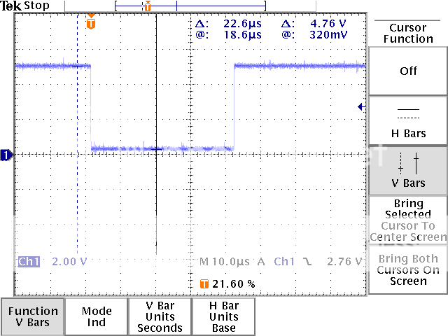
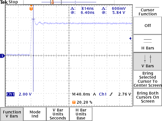
This is the pulse when connected to the DM856, width 41us, nothing fancy jumps out. The back of the pulse overshoots a bit, not sure whether that matters:
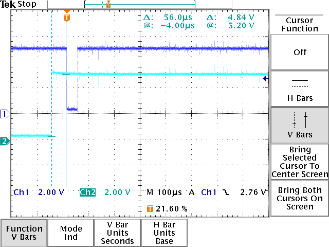
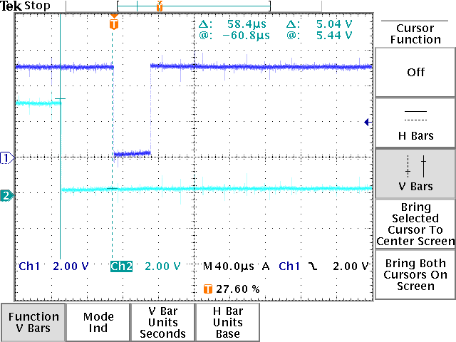
Here's a Pulse vs Dir screenshot, again around 55us difference between the two, DIR being changed first as per the manual:
Afterwards I followed Gary's (Zapp) suggestion and connected the PIC to a different driver, this time a bigger HBS86 coupled with a bigger Nema 34 motor (with an encoder). For starters I got a lot of noise on the pulse and direction lines, but I had all sorts of cables on the bench, crossed etc.:
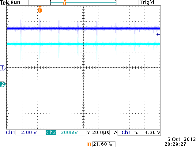
Here's a pulse vs direction screenshot, all looking steady (well apart from noise):
And here's a video showing how the motor moves when the buttons are pressed:
[video should work now]
Compared to the previous video this is steady, no jump backs, no sudden movement. A bit noisy I have to say, it clunks every time, but it's a bigger motor. Is this good behaviour?
I've started looking at the configuration of the DM856 but whenever I try to connect to the driver via RS232 it looses connection. I will try on a laptop at work tomorrow.
Regards,
T.Last edited by dsc; 16-10-2013 at 08:21 AM.
-
The Following User Says Thank You to dsc For This Useful Post:
-
17-10-2013 #14
Last Activity: 17-06-2020
Just a bit more info, here's the DIP switches on the DM856:

According to the manual this gives:
- 400 steps per rotation
- software configured dynamic current setting
- half current in standstill (or full, manual shows conflicting info for this)
Can anyone suggest buffering that would work on the outputs?
Regards,
T.
-
17-10-2013 #15
 Last Activity: 01-05-2026

So just to be clear, you are saying that it works fine with the HBS86 coupled with a bigger Nema 34 motor (other than noise) but it's not fine with the DM856 ?
The HC244 is often used as a buffer, it also has 2 active low output enables that can be used in a watchdog, E/stop, charge pump circuit.Last edited by EddyCurrent; 17-10-2013 at 11:45 AM.
-
17-10-2013 #16
Last Activity: 17-06-2020
Yes it seems that way, with the HBS65 and the big Nema 34 it seems to work fine ie.no glitches, steps seem complete and there's no erratic movement front / reverse. The big motor seems to be louder, there's a 'clunk' when it steps, but I'm not sure whether that's correct operation or not as I've never used steppers before. The small motor with the DM856 shows a lot of erratic movement when driven by the same signals from the PIC, even though the noise levels on that driver are much lower than the HBS86.
Regards,
T.
-
17-10-2013 #17
Last Activity: 17-03-2017
Looking at those traces there's nothing obviously wrong with the input to the driver, so the issue would seem to be with the driver, yet you say it works ok with a pulse generator?
Are the motors clamped down to the bench? I know my bench testing was noisy when the motor was just lying there.
Do you have PIC ground and motor supply ground tied together or separate?
What do you have on input & output of 7805 regulator?
-
17-10-2013 #18
Last Activity: 17-06-2020
Yes I've had it connected to a pulse generator earlier on, but of course that's a source output rather than a sink, it seemed to work ok I think, I will upload a video later on with a pulse genny on the DM856.
The motor just sits on a desk, I can probably clamp it down for further tests.
As I said before the PIC is powered from a plug-in 9VDC power supply, which is connected to the same 230VAC source as the 68VDC PSU which powers the motor / driver.
On the 7805 I have 9VDC on the input and 5.01VDC on the output.
Regards,
T.
-
17-10-2013 #19
Last Activity: 01-05-2026
Having read you previous posts I am surprised you say this
because it doesn't matter about that, it's the output dc grounds that have to be connected.As I said before the PIC is powered from a plug-in 9VDC power supply, which is connected to the same 230VAC source as the 68VDC PSU which powers the motor / driver.Last edited by EddyCurrent; 17-10-2013 at 01:55 PM.
-
17-10-2013 #20
Last Activity: 17-06-2020
Why is that? what I meant to say is that eventually it all comes down to the same 230VAC connection, so ground on both should be at the same potential. Or am I missing something obvious?
Regards,
T.

 Reply With Quote
Thread Information
Users Browsing this Thread
There are currently 1 users browsing this thread. (0 members and 1 guests)
Similar Threads
-
My turn for help with Pulse multiplier for test rig.
By JAZZCNC in forum Electronic Project BuildingReplies: 75Last Post: 20-06-2014, 06:09 PM -
MPG or Hand Wheel Pulse Encoder where to buy in UK?
By suesi34e in forum Marketplace DiscussionReplies: 5Last Post: 02-01-2014, 04:41 PM -
Pulse rate or dip switch settings
By Jopo in forum Stepper & Servo MotorsReplies: 0Last Post: 29-04-2013, 08:08 AM -
Strange problem, possibly missing steps?
By Philly in forum Chinese MachinesReplies: 5Last Post: 26-10-2012, 06:36 PM -
Missing Steps + Stalling X-axis
By danielbriggs in forum Linear & Rotary MotionReplies: 5Last Post: 02-09-2010, 02:59 PM

Bookmarks