
-
26-09-2014 #11

 Last Activity: 29-07-2017


Cheers Robin, I have seen that site from a previous post you made on another thread. Ebay is also a good place to find parts for molds there are a few chinese sellers selling ejector pins, springs and bushings, I dont have a link but they should be easily viewable.
Thanks for the heads up on purging deisel I was not aware of how toxic some plastics are when burnt or that you should not mix certain plastic together for safety.
The rabit takes molds bases that can be made on the lathe ie. cyclindrical not square, at some point someone has modded the machine to also accept bigger square or rectangle molds. The machine came with a manual with some basic dimensions and mold making tips. I will try and scan some important pages and see if anyone can help me work out how to cut the injector gate on the rear of the mold. CNC routing and prototyping services www.cncscotland.co.uk
 ADD ME ON FACEBOOKS
-
08-10-2014 #12
Last Activity: 29-07-2017
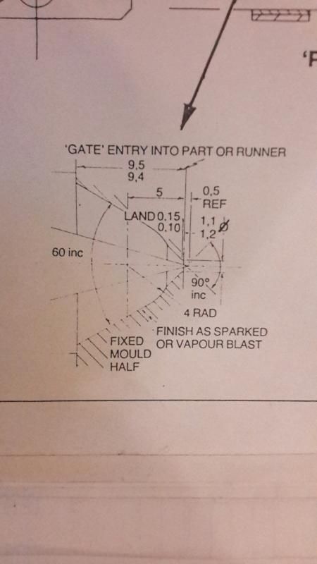
Any ideas on how best to machine this gate entry in the mold, the mold is cylindrical so I can use a lathe.
I can see 4 components to the operation,
1. 1.1mm hole
2. 4mm radius
3. 60 degree bore?
4. 90 degree bore?Last edited by gavztheouch; 08-10-2014 at 07:09 PM.
CNC routing and prototyping services www.cncscotland.co.uk
ADD ME ON FACEBOOKS
-
08-10-2014 #13
Last Activity: 3 Hours Ago

CNC lathe would be the simplest.
.
However, with a selection of drills, boring bar, 90deg countersink, and an 8mm radius ballend mill it could be acheived on a manual lathe.Avoiding the rubbish customer service from AluminiumWarehouse since July '13.
-
09-10-2014 #14
 Last Activity: 17-08-2025


Hard to see what is going on, is this where a plasticiser nozzle connects to a mould parting line?
I would not have thought it would be critical if there is no other inlet (insert "beats me, shrug" smiley here)
-
09-10-2014 #15
Last Activity: 29-07-2017
Robin - This is a diagram of the nozzle/injection entry on the rear of the mold. The 'small internal cone' I think is hot metal cone that keeps the plastic from setting in the entrance to the injector point. Is this what you call a plasticiser?
I think you are right that this is not so critical to get all the angles and rads just so. I think the only critical point would be the depth that the hot cone pokes into the mold specifically the 1.1mm diameter hole that feeds the mold cavitiy. If it goes in too far it will block the mold and if its too far away it might allow the plastic to set?CNC routing and prototyping services www.cncscotland.co.uk
ADD ME ON FACEBOOKS
-
09-10-2014 #16
Last Activity: 1 Week Ago
If you can get an engraving bit with the 60 deg angle you should be able to do it.
If you go over to http://www.model-engineer.co.uk/ and look up "D" bits this will show you how to make one from silver steel, drill your hole go in with the "D" bit to the required depth then tickle the hole with the engraving bit.
Good Luck
Mike
-
09-10-2014 #17
Last Activity: 29-07-2017
Thanks Mike,
Most center drills are 60 degree I think? Shame they have a that little drill point on the end (Maybe I could turn that down to continue the 60 degree shape?). Anyway I should be able to pickup a 60 chamfer or engraving tool.
So I think the plan would be.
1. Drill 1mm hole straight through. (Hopefully easy in alu?)
2. Use 60 degree tool to hog out material and form 60 shape.
3. Use a small 90 degree tool widen the 1mm hole entrance
4. Use 4mm rad ballnose to blend the 60 and 90 degree shapes by eye?CNC routing and prototyping services www.cncscotland.co.uk
ADD ME ON FACEBOOKS
-
09-10-2014 #18
Last Activity: 1 Week Ago
Yes first op is drill the hole, you then want to remove the bulk of the material as you would probably break the engraving tool if you tried to open it out with that, also just checked the angles the 60 deg is refering to the larger opening that blends with the 45deg, the taper that opens out the hole has an included angle of 30 deg so you need an engraving tool that size, so remove the bulk machining the 45deg taper then go in with your 8mm dia ball nose cutter then just blend out with the 60 deg taper and tickle out the 30 deg taper with the engraving tool. FYI a "D" bit is just a form tool you basically turn the required profile with the drive dia slightly offset then machine away the profile leaving it flat topped to the centre line of the driving diameter, this gives the profile a "D" shape and a cutting clearance.
Regards
Mike
Reg
-
09-10-2014 #19
Last Activity: 29-07-2017
I think the 30 degree taper is not part of the mold but instead part of the machine that injects the plastic. My thoughts are this is a heated tip and the plastic will flow around this?the taper that opens out the hole has an included angle of 30 deg so you need an engraving tool that size,CNC routing and prototyping services www.cncscotland.co.uk
ADD ME ON FACEBOOKS
-
09-10-2014 #20
Last Activity: 1 Week Ago
That makes it relatively easy to make then, carry on number one.
Mike

 Reply With Quote
Thread Information
Users Browsing this Thread
There are currently 1 users browsing this thread. (0 members and 1 guests)
Similar Threads
-
Plastic injection mold making forum?
By gavztheouch in forum Moulding MachinesReplies: 26Last Post: 13-10-2022, 11:31 AM -
New toy - Arburg injection moulder
By Robin Hewitt in forum Moulding MachinesReplies: 13Last Post: 26-10-2014, 11:59 PM -
RFQ: Any Injection Moulders on here, before I buy Chinese ?
By Bazzer in forum Projects, Jobs & RequestsReplies: 11Last Post: 18-05-2013, 11:25 AM -
DIY Injection moulding by JR Hartley.
By HankMcSpank in forum Moulding MachinesReplies: 26Last Post: 04-01-2013, 12:41 AM -
Proxxon MF70 for making injection molds
By forrest in forum Moulding MachinesReplies: 8Last Post: 11-04-2012, 11:30 PM

Bookmarks