Hybrid View
-
05-03-2015 #1
Hi guys,
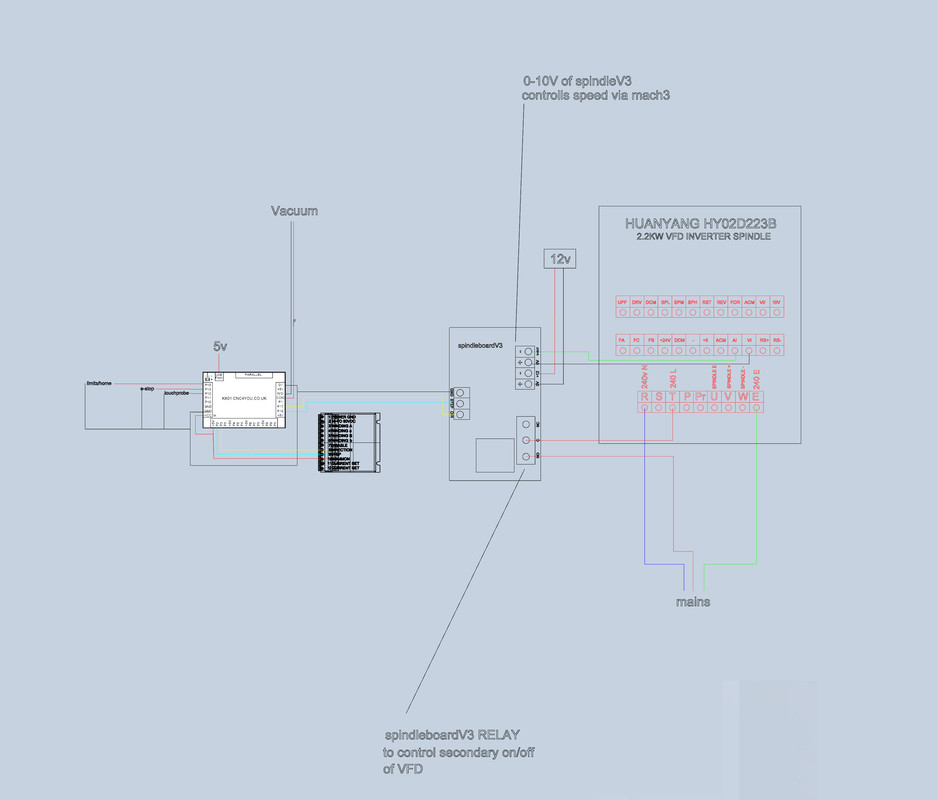
I just bought the KKO1 BOB, I'm trying to to hook it up to the DIYCNC spindle board and then onto the VFD so i can have Mach 3 Control. I would also like to use the spare relay from the KK01 for on/off of a vacuum table lets say. Is any one able to confirm the wiring it correct. I really don't want to blow up any more components. the two links below are for the manuals. many thanks
pic host
https://www.mediafire.com/?rc61wkf8r4m4or6
https://www.mediafire.com/?rc61wkf8r4m4or6Last edited by rbs; 05-03-2015 at 06:42 PM.
-
05-03-2015 #2
Hold on ! Looks like you are switching the spindle on and off at the mains input to control it. If you want to start and stop the spindle this is not a good idea! Leave the VFD powered directly from the mains all the time and control it using the green inputs on the control panel - the row of small terminals above the mains and spindle connections.
Here is the schematic:
This is how I think it should work:
Start / stop = connect relay terminals to FOR and DCM. The relay makes or breaks this circuit.
To get this to work you also need to set PD001 to 1 (from memory) to tell it to use this external control.
Speed control (manual) = connect a 3 pin potentiometer (say 10k) with one outer pin to VR, the opposite pin to ACM, and the middle pin to V1.
To get this to work you also need to set PD002 to 1, and set the little jumper (on the right side of the green input panel) to VI to tell it to use the external control
Speed control (auto with voltage control) = connect 10V from BoB to V1 (as you have drawn it), and 0V to ACM (not as you have drawn it to A1 which is for current control and it looks like your BoB is outputing a variable voltage)
-
06-03-2015 #3
Hi OK, thanks for that and the extra info.
for the interest of this thread I've redone the schematic just so there's no one else following committing to fry their electronics.
Does this look correct? Many thanks
free image uploading
-
06-03-2015 #4
Hi rbs
Your new sketch still looks wrong on the speed control part. If the spindle control board is putting out a variable 0-10V to control the speed then in my view:
+ on the board should go to VI on the VFD
- on the board should go to ACM on the VFD
Don't connect anything to VR or AI for what you are trying to do.
Also, note that the manual shows a grounded shielded cable for the control cable (the dotted hoop around the input lines) to reduce interference.
*If any moderators are reading this it is probably more appropriate to move it to the electronics > VFD section . . .*Last edited by routercnc; 06-03-2015 at 10:47 PM.
Thread Information
Users Browsing this Thread
There are currently 1 users browsing this thread. (0 members and 1 guests)
Similar Threads
-
BUILD LOG: a Steel Box Section Build with SBR20 & Ballscrews Plus a few questions
By grain_r in forum DIY Router Build LogsReplies: 130Last Post: 27-01-2023, 06:47 PM -
Plasma table build, first question....
By Davek0974 in forum Plasma Table MachinesReplies: 51Last Post: 01-08-2014, 03:11 PM -
Wiring Help
By Toddy in forum Motor Drivers & ControllersReplies: 8Last Post: 23-11-2010, 01:48 PM -
Limit switch wiring question ...
By Wobblybootie in forum General ElectronicsReplies: 20Last Post: 31-10-2010, 11:06 AM -
wiring help
By ste68blue in forum Stepper & Servo MotorsReplies: 6Last Post: 29-07-2009, 10:23 AM
Bookmarks