
Thread: Hybrid Mill Design
-
29-11-2015 #1

 Last Activity: 4 Hours Ago


Hi,
So I would like to get a larger mill that is designed mainly for cutting Aluminium. This means high speed spindle and fairly quick feed rates.
Heavily inspired by this design (http://uk.dmgmori.com/blob/172034/d7...0-pdf-data.pdf), see pages 4 to 7, I came up with the following design. This is also very similar to the Ultimaker 3D printer design where you have a 'box' and you keep all the movement on top and place everything centrally over the table.
The design is drawn using 1605 Leadscrews (C5 grade) and 400W Servo Motors (4, 5 or 6) - Cant decide if Z and Y need 2nd screws or not. Rails are Hiwin 20 (for Z) and 25 for X and Y.
The spindle will be a 4KW Chinese Watercooled spindle.
Cutting size based on the design is around X and Y - 600 mm x 600 mm x 250 mm.
For the frame, I want to look at using something 'interesting' like Epoxy Granite or something similar. For any parts that are needed, these will be done out of either steel or aluminium.
Thoughts / critique welcome. Thanks.
Last edited by Chaz; 29-11-2015 at 05:06 PM.
-
29-11-2015 #2
Last Activity: 17-05-2026
Chaz - can't help with any of your questions but I've seen that you are using Fusion 360 for this design. I'm using the same thing (and gradually getting to grips with it) although I haven't looked at any fancy renderings yet! However, can you give a pointer to a source of the Hiwin carriages and rails? Are these from Hiwin, and what drawing format works for you?
Thanks,
-
29-11-2015 #3
Last Activity: 4 Hours Ago
Hi, how did you know it was Fusion? Hehe.
 Originally Posted by Neale

There is a place that I found the CAD documents on .... I import them as STEP file IIRC.
http://hiwin.partcommunity.com/ - you need to register, quick and easy.
-
29-11-2015 #4
Last Activity: 17-05-2026
Because you mentioned it in another post! I thought the question fitted better here, though. Many thanks for the answer - I'll go take a look. Originally Posted by Chaz
I have to say that things like F360 make 3D CAD much more accessible even to a novice amateur like me, and your pictures above are a great demonstration of what can be done.
-
29-11-2015 #5
Last Activity: 1 Day Ago


I have just been watching a video here https://www.youtube.com/watch?v=o-GBpUZ3piY If you have used SW it seems very easy to use. I am impressed and will give it a try.
..Clive
The more you know, The better you know, How little you know
-
29-11-2015 #6
Last Activity: 4 Hours Ago
Any comments on my mill design ;p ?
-
29-11-2015 #7
 Last Activity: 1 Week Ago

Hi Chaz,
Some thoughts -
1.The plates which hang off the Y axis (and hold the Y bearings) look weak as they cantilevered off the side.
2. How will you clamp the spindle? Are you planning on using grub screws? Not sure that is a good idea.
3. Are you only using 1 bearing per rail on the Z axis? I would use 2 per rail.
4. I would use 2 screws on Y to get the most out of a machine like this.
5. 2 screws in Z is worth looking at but it takes up Y travel and I think one screw is still pretty good.
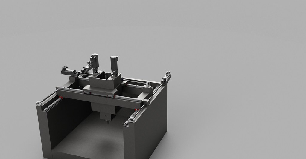
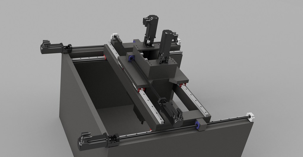
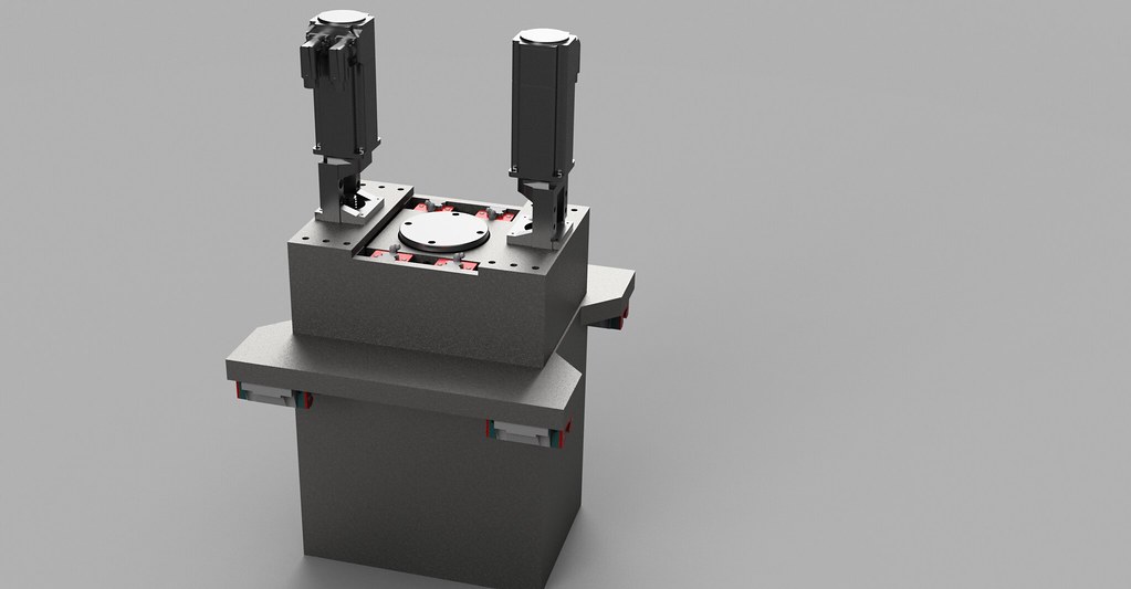
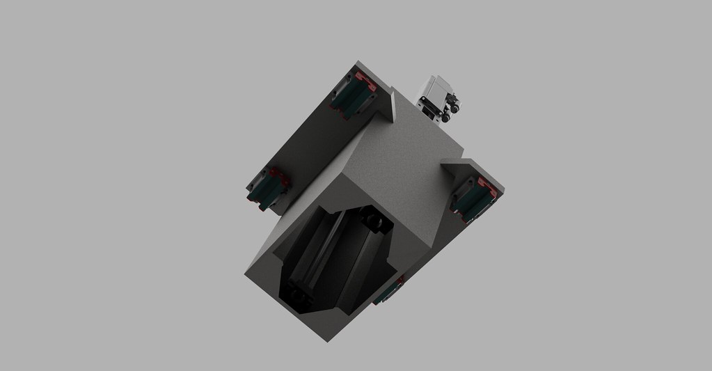
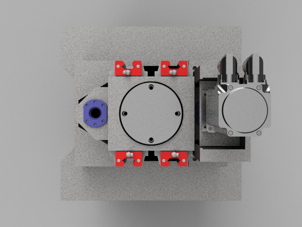
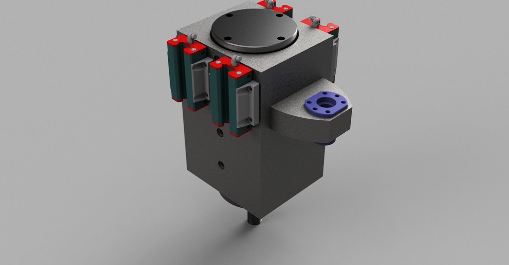
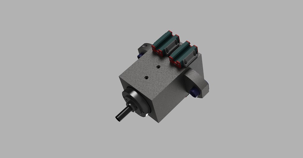
I've also been working on a new design over the past few weeks based on the DMG Mori - here is my attempt so far:
Iso metric:
Side:
Top:
Y axis:
Box Z axis:
Underside of Z axis showing spindle clamped by front plate:
-
30-11-2015 #8
 Last Activity: 21-08-2020

Yes, forget it. How big should the machine be?
That dubious concept isn't as easy as it looks. I think they have a gantry Axe on Y (if the normal X-Y is correct) only, because Hermle have a patent for a centralised Spindle. Gantry have no advantage against 1 spindle in the middle, except in a really large machine.
And your control must handle 3 of it. Can it do this.
The same for X and Z. This construction is ok, if you have a spindle with a ton or more. If not its much too complicated.
And the Z axe don't work, you have 4 guiding carriage (I hope the word is correct, the slider on the linear guide) 4 or eventually 3 is correct, but not in these layout.
You need 2 sliders per linear guide. And if you want 4 side by side each must
parallel within a rather tight tolerance.
If its for yourself and you don't want to sell it, then you can make it with a central spindle.
A gantry spindle brings no advantage, but much more effort, each Motor and driver must bought double.
The concept with the u-shaped bed is good, but all other too complicated. Unfortunately I don't know, how I can add a pdf-file.
-
30-11-2015 #9
Last Activity: 4 Hours Ago
Thanks. I understand most of what is being said. Ill respond later when I have a bit more time regarding some questions. Originally Posted by uli12us
Please email me the pdf - ctintinger at gmail dot com.
Thanks
-
30-11-2015 #10
Last Activity: 06-07-2022
Chaz,
You seem to have money to spend on this which is why I am keen to see what you come up with. My suggestion on the spindle arrangement is to make the box section adjustable so that you use two of the rails as data to bring the other two in to take up the tolerances.
Getting two carriages per rail should go without saying, but you may get away with two per rail on the back and one per rail on the front.
Do you have the powersupply for the 4KW spindle?https://emvioeng.com
Machine tools and 3D printing supplies. Expanding constantly.

 Reply With Quote
Thread Information
Users Browsing this Thread
There are currently 1 users browsing this thread. (0 members and 1 guests)
Similar Threads
-
Hybrid Stepper Servo
By Boyan Silyavski in forum Motor Drivers & ControllersReplies: 0Last Post: 08-06-2015, 12:41 PM -
Interesting Mill Design on Hackaday
By epninety in forum Milling Machines, Builds & ConversionsReplies: 4Last Post: 01-03-2014, 05:10 PM -
Building a hybrid CNC mill. Need advice and recommendations
By oldmam4m80s in forum Milling Machines, Builds & ConversionsReplies: 8Last Post: 16-08-2013, 07:11 AM -
Hybrid gantry
By routercnc in forum Gantry/Router Machines & BuildingReplies: 5Last Post: 17-04-2012, 08:09 PM -
Small Mill very early design stage
By leadinglights in forum Milling Machines, Builds & ConversionsReplies: 29Last Post: 15-06-2010, 01:05 AM

Bookmarks