Thread: Hybrid Mill Design
-
30-11-2015 #11
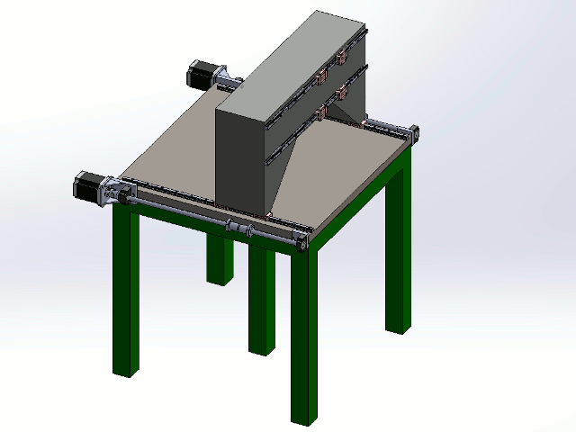
Agree with that. My plan was for the green sections on the Y axis to have the vertical end plates arranged so that I can fix one pair of carraiges and then 'slightly pre-load' the other plate up to the opposite side so everything is aligned. This assumes the machining on the Z axis plates is good where the rails sit.
-
30-11-2015 #12
The reason for the grub screws to hold the spindle was that I did not want to distort the 'box' by slotting it and then clamping the spindle but wasnt sure if the grub screw method would work.
The same for the 4 way / 4 carriage system. Im not sure how the Octagon system works on the benchmark mill .... need more info / pics and google hasnt helped.
This is why we get feedback :-)
-
30-11-2015 #13
Seem to :-)
The idea was built out of getting something very rigid. I like the design and if you follow this thread (http://www.cnczone.com/forums/vertic...-posts-16.html) that is the material type I wanted to use.
I believe that in most cases the machines that are made by Datron and Mori Seiki are either cast iron or some form of epoxy / cement type material.
For the spindle, yes, Im running a 32A feed on single phase. Plus, the likelyhood of using all 4KW is low.
-
30-11-2015 #14
-
30-11-2015 #15
Ok, it works I hope. Here is the only flyer I found, where you can see, how the hermle machines were build. On page5 there is a gantry construction and page 7 shows the normal construction. These machines run since 15Years or so, without problems. The spindle for the Y-Axe is hidden behind the spindlehead in the middle of the X-axe. I don't know exaktly, but I think in this case the have a stationary spindle and a driven nut. The only obvious disadvantage of these construction is, you need at least the complete Y-way free space behind the machine.
The flyer is free downloadable on the hermle homepage, so I think its ok, I post it here, without any copyright issues.
-
30-11-2015 #16
-
30-11-2015 #17
1.The plates which hang off the Y axis (and hold the Y bearings) look weak as they cantilevered off the side.
They could be improved / widened, would that still be a concern?
2. How will you clamp the spindle? Are you planning on using grub screws? Not sure that is a good idea.
Agreed, not sure either. Problem is, how do you ensure that the square remains perfectly square (for the rail system) when you tighten to clamp the spindle?
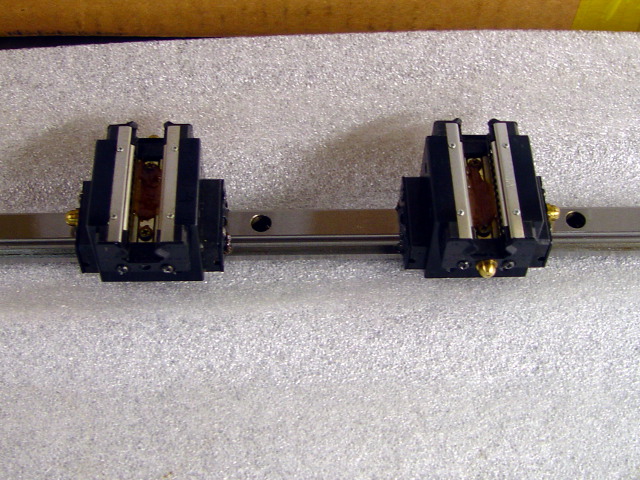
3. Are you only using 1 bearing per rail on the Z axis? I would use 2 per rail.
Understood / agreed.
4. I would use 2 screws on Y to get the most out of a machine like this.
Understood / agreed.
5. 2 screws in Z is worth looking at but it takes up Y travel and I think one screw is still pretty good.
Fair point, I was looking at this to mitigate for only having 4 carriers. I dont really want to go to 8 and I like the idea of a square / Octogon shape for strength. Suppose a traditional design might be better.
-
30-11-2015 #18
Hi Chaz,
If you look at my design the side plates are braced back to the main Y axis assembly with effectively triangular structures. There is also a closer plate (see Y axis picture) to create a local box structure, which also provides stiffness for the Y ballscrew to connect to. On your design some triangular bracing pieces could work with a notch / clearance area at the inside corner to clear the ballscrew.
I thought alot about the spindle clamping and problems with keeping the rails aligned. In the end the spindle clamp is quite small, and the plate on the bottom surface is fixed (the transparent piece in the last picture), plus the front plate above the spindle is also fixed. This should keep the rails aligned whilst adjusting / clamping the spindle. Look at the last picture I posted for my thoughts on how to do it.
I drew loads of single and twin Z axis ballscrew arrangements but could not get a compact package with twin screws, so after agonising over it went back to single which has the smallest offset from the centre line I could achieve.
As for the Z axis bearings on the dmg machine - I don't know this for a fact but I can't see any Z rails so my conclusion is that is runs on a finely ground flat surface on the hexagon faces - bit like the ways on a mill / lathe but flat and trapped on all sides. You can see some sort of pre-load screw(?) or oiling point so perhaps it also has a film of high pressure oil in there like an engine crank/big end. Really just guessing here so would welcome thoughts from others on this. Either way, probably not a DIY solution.
-
30-11-2015 #19
Thanks. I think you might be 100% correct, perhaps its a 'perfect' fit solution - would be lovely.
Taking some inspiration from this thread, gantry design with epoxy. (Dutch thread). http://www.cnczone.nl/viewtopic.php?f=8&t=8410

Look at the speed on this - https://www.youtube.com/watch?v=rtJ3MGSM030 and it looks fairly rigid.
This also looks interesting -
-
30-11-2015 #20
This is the same machine cutting steel.
https://www.youtube.com/watch?v=0etcYg6S0dU#t=74
Thread Information
Users Browsing this Thread
There are currently 1 users browsing this thread. (0 members and 1 guests)
Similar Threads
-
Hybrid Stepper Servo
By Boyan Silyavski in forum Motor Drivers & ControllersReplies: 0Last Post: 08-06-2015, 12:41 PM -
Interesting Mill Design on Hackaday
By epninety in forum Milling Machines, Builds & ConversionsReplies: 4Last Post: 01-03-2014, 05:10 PM -
Building a hybrid CNC mill. Need advice and recommendations
By oldmam4m80s in forum Milling Machines, Builds & ConversionsReplies: 8Last Post: 16-08-2013, 07:11 AM -
Hybrid gantry
By routercnc in forum Gantry/Router Machines & BuildingReplies: 5Last Post: 17-04-2012, 08:09 PM -
Small Mill very early design stage
By leadinglights in forum Milling Machines, Builds & ConversionsReplies: 29Last Post: 15-06-2010, 01:05 AM


 Reply With Quote


Bookmarks