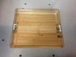
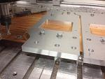
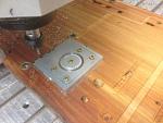
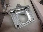
OK, more updates. To finish off the info on the bed rail supports, here is the little jig I made up to hold the bosses in place:
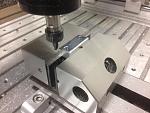
Here it is in position:
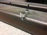
It uses 6mm shoulder bolts to give a good reference position and picks up off the inner tapped hole already there. This holds the boss in just the right place for welding. It's now ready for welding - just need to catch my friend with the welder in the next few days or so. This is bolt down the supported rail which obviously uses a pair of bolts on either side of the flange.
I've also taken the opportunity to spot out the holes for a profiled rail (i.e down the middle) to make a future upgrade much easier to do.
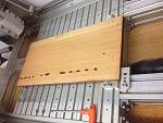
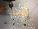
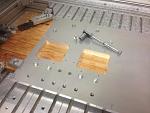
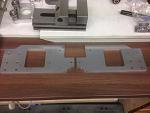
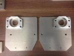
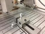
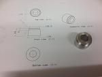
Next up are the end plates which hold the motor mounting plates. Starting with a nice skimmed off the sacrificial board:
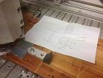
Then setting up:
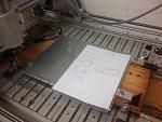
(note that I've scribbled down the X, Y, Z coord of the workoffset on the drawing - I always write them down in case of power failure)
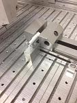
I'm making a mirrored pair here. A few holes, and a large pocket in the middle of each one. You can drill and screw through the waste first, but and I'll talk you through my approach on the large cutout as it worked quite well as an alternative. This is all to avoid those terrible tool witness marks from tabs.
1) Use an inside profile with a 1mm offset (remaining stock on the side wall) WITH TABS.

2) Then drill through the tabs with a cordless drill to remove the waste:
3) Manually jog the machine to remove most of the tabs (not critical to get all of it)
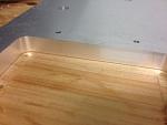
4) Clean up profile pass to remove the last 1mm. I do this in 2 stages as this is what works for my machine. 1st cleanup 3mm DOC, 0.9mm WOC, final cut full DOC, 0.1mm WOC.
Gives this surface finish:
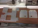
Then bolting down, removing clamps, and onto the profile cut:
Same approach as above using a rough cut leaving 1mm stock, then semi-finish 3mm DOC, 0.9mm WOC, and finish full DOC, 0.1mm WOC. A stiffer/better machine might do the finish in one pass. I'm also limited to 6mm max cutter on ER11 collet. Good finish anyway:
Mirror part cut the same way, then some holes tapped and surface cleaned up:
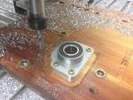
The bearing end plates were done in the same way:
Then onto the bearing holders:
They will be a light press fit:
Second one made:
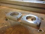
Trial fit onto the bearing plates:
This allows the ballscrew end bearing position to be fine tuned when setting up.
__________________
Moving away from the X axis and onto the Y axis - the belt tensioning system progresses. Turned some standoffs to hold the adjustable belt guide bearings:

______________________________
Looking ahead I need to turn down the end of one of the ballscrews. Made these 2 bits to hold it in the lathe. First is a protective collar to stop the jaws damaging the ballscrew:
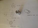
Made it by boring a hole into some round stock on the lathe.
Then machined a hex onto some round stock:
Then used the hex to give 120 degree spacing to machine the 3 slots. Don't have a hex collet block which would have done the job!
Then back to the lathe to part it off:

Then to support the end of the ballscrew as it passed out of the headstock a spider/collar to fit inside the lathe spindle bore and hold the ballscrew. The ballnut is then 'tightened' up against it. Copied the whole idea off Youtube so should be OK!


 Last Activity: 26-08-2025

 Very awesome, loving the work you are doing.
 Originally Posted by routercnc


 Reply With Quote
Bookmarks