
Thread: Cnc for dummies
Hybrid View


-
28-06-2009 #1

 Last Activity: 23-09-2017


OK I'll try in words of 1/2 a syllable.
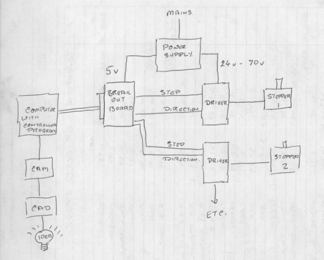
Start bottom left with an idea of a part. This is then turned into a drawing in a CAD program, passed to a CAM program that writes the G Code and then loaded into a PC that also runs a controller program like Mach3 or EMC.
This in turn spits out a series of electrical commands via the parallel port to a breakout board.
The purpose of this is to protect the computer from any unwanted reversed voltages and also to get a clean signal as a lot of computers output low voltage on the parallel ports and this boosts the signal.
The clean signal is now sent on to a driver who's job it is to amplify the small logic signals into heavier current for the motor. Simply put you get two wires per driver, step and direction.
step is a pulse that makes the stepper motor work, most require 200 full steps per motor revolution. Direction is which way it has to go.
From the driver the current goes down the cables to the motor, motor is connected to an axis.
In the drawing only two are shown but more is only a duplicate of driver and motor.
Looking over all this is a power supply that gives various voltages out as needed for the components, the main one being the stepper driver supply.
Very rough and ready and can be expanded on but that's the basics.
.John S -
-
04-07-2009 #2

 Last Activity: 05-09-2009
Very helpful,sorry abut the delay in answering, just got back from hols.
Last Activity: 05-09-2009
Very helpful,sorry abut the delay in answering, just got back from hols. Originally Posted by John S


-
04-07-2009 #3
Last Activity: 05-09-2009
This is just the type of info. needed to decide whether to proceed with a project. Being of somewhat advanced years i take a little longer to absorb tech. info. these days, and i appreciate your time and approach o the question. I now need to research info. on the various steps you have described.Many thanks again.
Dave.

 Reply With Quote
Thread Information
Users Browsing this Thread
There are currently 1 users browsing this thread. (0 members and 1 guests)
Similar Threads
-
BUILD LOG: CNC for dummies...Some electrics advice please...pretty please...
By andy586 in forum DIY Router Build LogsReplies: 6Last Post: 01-06-2014, 11:13 AM -
Lathe / Milling for dummies
By kingcreaky in forum Milling Machines, Builds & ConversionsReplies: 5Last Post: 04-12-2012, 01:54 PM

Bookmarks