
Thread: edge finish - ripples and ridges
-
06-07-2013 #1

 Last Activity: 17-06-2020


Hi everyone,
got some parts cut by a friend of a friend, as it's a favor I don't want to start moaning, but I've noticed a few strange things on the edge finish (cut is done in 15mm ali):
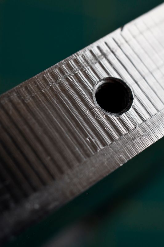
1. ripples - is this simply a cut done too fast?
2. seems like the cut was done it two steps, really deep (around 12mm) and finishing cut to go all the way through (the remaining 3mm).
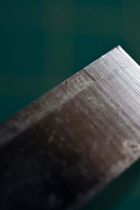
3. the beginning of the cut seems like 'single', but a few mm later transitions to a two step cut. Am I correct to think that it was started as a single, full depth cut, but due to this being too much for the machine, it was split and done in to cuts instead?
The ripples I can live with, it's only really on a single element, but the two-step cut causes problems as it creates a ridge in the lower part of the edge, which means that instead of nice flat edge surface, I end up with something a bit wonky.
Cheers for any pointers or additional info.
Regards,
dsc.
-
07-07-2013 #2
Last Activity: 19-05-2025
i have limited experience but it looks like they just ripped through it,looks in the first picture to be cut from both sides maybe a mistake was made and the part was flipped to start again but the 3mm pass you mention looks( in the last picture) to be the first past rather than finishing past as it looks undercut to the 12mm pass.has it been done on a cnc or a manual mill.
Last edited by dazza; 07-07-2013 at 12:30 PM.
-
07-07-2013 #3
Last Activity: 17-06-2020
Thanks deisel, this was a CNC cut. To me it looks like it was cut too fast and too deep, with 15mm ali, I thought you'd want around 5mm depth on all passes, so three passes min.
Regards,
dsc.
-
07-07-2013 #4
 Last Activity: 19-01-2024

The ripples are very bad chatter from cutting deep or a weak machine flexing. These often happens when roughing out and why you should always have a finish pass if it matters.
The ridge will be caused by the cutter springing with the difference between deep and shallow cut. Chances are the cutter used didn't have enough flute length to cut 15mm so did pass in 2 but mistake being they used deep pass followed by shallow instead of breaking in half to relieve spring on cutter.
A finish pass with a small 0.1mm or so step over to clean up would have sorted this and left nice finish, even with short flute length cutter has there is very little pressure on cutter so no spring on cutter.
Usually if you run over flat belt sander the ripples are knocked off easy enough.
-
The Following User Says Thank You to JAZZCNC For This Useful Post:
-
07-07-2013 #5
Last Activity: 17-06-2020
Thanks Jazz. The other issue is that the parts were suppose to be 15mm +/- 0.1mm, but are in fact 15.2mm - 15.25mm. Any chance of bringing them down to 15mm, so taking 0.2mm of the top?
The ripples are only visible on a single edge on one part, so not a biggie, but the ridge is present in more than 50% of edges.
Regards,
dsc.
-
07-07-2013 #6
 Last Activity: 1 Day Ago

 Yea the same...looks like a rush job.
 Originally Posted by dsc

.MeLee
-
07-07-2013 #7
Last Activity: 19-01-2024
If your asking me can I take material off for you then sorry no can't for reason's won't go into here. Originally Posted by dsc
But if your just asking if think it's possible then yes they just need skimming over with fly cutter.
To be honest if cut from rolled Alu plate then chances are it's not truly flat so would need both sides skimming and with only 0.2 to play with then would be touch and go if you'd have enough material to cleanly do both sides.
If you mean 0.1-0.2 oversize and can profile shape be machined to dimensions then yes it's possible but very difficult and timely to re-position on machine to such fine tolerance.
It would need 2 or 3 good clear reference points to work off and lot of messing around with positioning into correct place because with only 0.1-0.2mm to work with there's no room for error.!
-
The Following User Says Thank You to JAZZCNC For This Useful Post:
-
07-07-2013 #8
Last Activity: 17-06-2020
Simply curious if it's possible to skim it or not, but I guess it's just not worth it at this point.
Another question I've got is slightly out of topic for this thread, but I'll go ahead and ask anyway. I have a bearing housing which seems to be the correct diameter if measured across x axis, but 0.1mm smaller when measured across y axis. What would cause such an error? runout on a lathe? it simply seems elliptical rather than round.
Regards,
dsc.
-
08-07-2013 #9
 Last Activity: 05-04-2020
That's a clear example of trying to cut faster than the machine, or tool, is good for. The wavy lines could also be caused by severe resonance ... either way a finishing pass would have sorted it out.
I could skim the parts for you, but it's not a quick job unless they're quite small.
Backlash, or more precisely - greater backlash in one axis. Bearing housings should really be bored, not milled, since even if you have a rigid machine with zero backlash the pocket will end up something other than a circle. The bore doesn't have to be out by much for you to either just have a loose fit, or worse distort the outer ring of the bearing causing it to wear prematurely. If I'm cutting a part on the CNC Router which includes a bearing, then I generally either bore it completely on the lathe or if it's a big bearing mill the pocket to 0.5mm undersize and then bore it. Originally Posted by dsc
-
The Following User Says Thank You to Jonathan For This Useful Post:
-
08-07-2013 #10
Last Activity: 17-06-2020
I would really only need skimming two parts as these are the plates where the the variable thickness adds to the overall depth of the whole construction and makes the side mounting holes move out of alignment.
As for the bearing housing, this was done on a lathe :O
Regards,
dsc.


 Reply With Quote
Thread Information
Users Browsing this Thread
There are currently 1 users browsing this thread. (0 members and 1 guests)
Similar Threads
-
How to get this finish..?
By Wal in forum Metal Finishing TechniquesReplies: 15Last Post: 02-02-2017, 11:08 PM -
Ridges in 3D profiles = hair loss and lots sandpaper
By Shinobiwan in forum Machine DiscussionReplies: 9Last Post: 11-04-2013, 07:45 PM -
Can you identify this paint on metal finish..?
By Wal in forum Metalwork DiscussionReplies: 2Last Post: 29-01-2013, 06:25 PM -
Better finish
By luke11cnc in forum Wood Finishing Tips & TricksReplies: 20Last Post: 27-03-2012, 11:25 PM -
Need advice on surface finish
By FatFreddie in forum Machine DiscussionReplies: 4Last Post: 01-05-2010, 02:51 PM

Bookmarks