
Hybrid View


-
06-03-2015 #1

 Last Activity: 09-07-2016


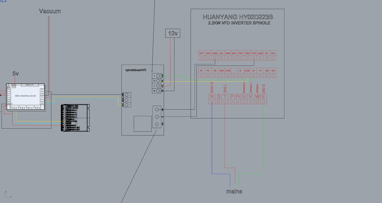
Hi OK, thanks for that and the extra info.
for the interest of this thread I've redone the schematic just so there's no one else following committing to fry their electronics.
Does this look correct? Many thanks
free image uploading
-
06-03-2015 #2
 Last Activity: 2 Days Ago
 Hi rbs
 Originally Posted by rbs

Your new sketch still looks wrong on the speed control part. If the spindle control board is putting out a variable 0-10V to control the speed then in my view:
+ on the board should go to VI on the VFD
- on the board should go to ACM on the VFD
Don't connect anything to VR or AI for what you are trying to do.
Also, note that the manual shows a grounded shielded cable for the control cable (the dotted hoop around the input lines) to reduce interference.
*If any moderators are reading this it is probably more appropriate to move it to the electronics > VFD section . . .*Last edited by routercnc; 06-03-2015 at 10:47 PM.

 Reply With Quote
Thread Information
Users Browsing this Thread
There are currently 1 users browsing this thread. (0 members and 1 guests)
Similar Threads
-
BUILD LOG: a Steel Box Section Build with SBR20 & Ballscrews Plus a few questions
By grain_r in forum DIY Router Build LogsReplies: 130Last Post: 27-01-2023, 06:47 PM -
Plasma table build, first question....
By Davek0974 in forum Plasma Table MachinesReplies: 51Last Post: 01-08-2014, 03:11 PM -
Wiring Help
By Toddy in forum Motor Drivers & ControllersReplies: 8Last Post: 23-11-2010, 01:48 PM -
Limit switch wiring question ...
By Wobblybootie in forum General ElectronicsReplies: 20Last Post: 31-10-2010, 11:06 AM -
wiring help
By ste68blue in forum Stepper & Servo MotorsReplies: 6Last Post: 29-07-2009, 10:23 AM

Bookmarks